I finally got around to changing the template for the blog since I was not happy with how the old version looked. Now everything should be a bit easier on the eyes and hyperlinks show up much better now.
Please let me know if there is anything I forgot to change or something else that I did not notice. Hope you like it!

A blog about the MSP430 LaunchPad from Texas Instruments for both beginners and experts.
Wednesday, March 23, 2011


Sunday, March 20, 2011
The DEV.BO is Born!
I would like to introduce you all to the DEV.BO prototype. This board is built around the MSP430F5510, it not only includes the typical on-board items, but also an FTDI chip.
As I have mentioned in previous posts, I was using the MSP430F5528 in a personal project of mine (which I will be posting when I have more time). TI just released a new set of chips in the MSP430F55xx series, one of which caught my eye, the MSP430F5510. This chip has all of the features I needed the 5528 for, but is half the price! Granted the 5510 does has less memory and a less precise ADC (and is lacking a few other things) but this was not important to my project.
Note: The MSP430F5510 on the DEV.BO is the 48 pin version which has a bit less peripherals than the larger sized MSP4305510 package.
I needed to get a board made for my project and decided to just go ahead and make a small target board which I might start selling if all goes well. Keep in mind this just a prototype and I need to test at least one more version before I can start selling them.
Some DEV.BO’s Features
I am still here and working hard, sorry that my last posts have been quite sporadic. I love how the DEV.BO came out and am excited to get it more finalized in the upcoming weeks. It makes programming the 5510 a breeze because of how simple it is to connect to the LaunchPad. I was very frustrated with my MSP430F5528 target board and how many wires I needed to get things up and running. Mouser just got the MSP430F5510 (in the correct package) in stock, so I can start pushing things along.
The reason I wanted to post this now was because my next two posts will be about one of my latest mini projects - a heart beat detection algorithm implemented on an MSP430F55xx. Once I finish those posts I will delve into the details of I2C because it can be a very confusing topic for beginners (and even advanced developers!).
 |
| The Dev.BO |
Note: The MSP430F5510 on the DEV.BO is the 48 pin version which has a bit less peripherals than the larger sized MSP4305510 package.
I needed to get a board made for my project and decided to just go ahead and make a small target board which I might start selling if all goes well. Keep in mind this just a prototype and I need to test at least one more version before I can start selling them.
Some DEV.BO’s Features
- Based on the MSP430F5510
- Max clock speed of 25MHz
- Integrated 32kHz crystal
- 25K of flash memory
- 1 USCI_A (UART/LIN/IrDA/SPI)
- 1 USCI_B (I2C/SPI)
- 2 16-bit (3CCR), 1 16-bit (5CCR), 1 16-bit (7CCR)
- 10-bit SAR ADC
- Much more!
- Connectors for both SBW and JTAG
- USB interface (FTDI323RL)
- 1 programmable push button
- 1 programmable LED
- Much more!
 |
| DEV.BO size comparison |
As you can see in the picture above, it is quite small. For me, it replaces the MSP430F5528 target board on the right and the FTDI breakout board from SparkFun on the upper left.
I am still here and working hard, sorry that my last posts have been quite sporadic. I love how the DEV.BO came out and am excited to get it more finalized in the upcoming weeks. It makes programming the 5510 a breeze because of how simple it is to connect to the LaunchPad. I was very frustrated with my MSP430F5528 target board and how many wires I needed to get things up and running. Mouser just got the MSP430F5510 (in the correct package) in stock, so I can start pushing things along.
The reason I wanted to post this now was because my next two posts will be about one of my latest mini projects - a heart beat detection algorithm implemented on an MSP430F55xx. Once I finish those posts I will delve into the details of I2C because it can be a very confusing topic for beginners (and even advanced developers!).
Sunday, January 9, 2011
Getting a PCB Made
I was recently asked where I get my PCBs made and realized that many people do not know of the great online PCB services which are available to hobbyists.
A few months ago I needed to get a PCB made for the first time in years and started the search for cheap places to get my board manufactured quickly with reasonable tolerances. I needed small quantities of a duel layer, surface mount, board with solder-mask and silkscreen on both sides. This usually adds more money to a PCB order than I was willing to spend on my small quick prototype board.
I found three services which met my cost requirements and did not have an unreasonable lead time. Here are my thoughts and a review on the PCB service I used.
MakePCB.com
http://makepcb.com/
This was the first board house I found which has reasonable pricing and a simple online quote system that you do not need to sign up for. I hate those websites where you have to give your personal information in order to receive a quote. This option seemed to be the best for me while I was living abroad since shipping to Europe was the same as the US. I ended up not using this service because there was no information on the website about how long it takes get your board. The major benefit to using this service is that if you want medium sized quantities the pricing scales very well. Check out their online quote calculator.
If anyone has used this service, send me a note or comment here. I'm very interested to see if anyone has had a good experience with this board house.
BatchPCB
http://batchpcb.com
This is a service run by SparkFun electronics and seems to be a great option when you do not need a board quickly. As with MakePCB, I ended up not using this service. On their FAQ page they say that it takes anywhere from 3 weeks to 4 weeks to receive your board. For the price this is very reasonable - considering most hobby projects are usually not time critical. One great feature of this website is that they save your board design and you can get new boards made at less cost; you can even sell your designs!
The pricing is "$10 setup fee (shown as a handling charge) - $2.50 per square inch for 2 layer designs". This makes the pricing better for larger boards than the last service I mention here.
This site has great reviews from a multitude of people. Check out this forum for more reviews and information on the service.
Dorkbot PCB Group Order
http://dorkbotpdx.org/wiki/pcb_order

This service works in a similar way as BatchPCB does. The person who runs the website fills up a large panel with multiple orders from hobbyists in order to keep costs very low. They are very helpful and answered all the questions I had; they also check to make sure your design is saved in the right format for their process and the boards are spaced properly. They send the boards out as soon as a panel fills up or a certain date has passed. Recently the boards have been filling up quickly and there has been more than one order per month.

This service is great for very small sized boards, which is a major reason I used this site for my boards. My board size was slightly more than 4 square inches and my design was ready a few days before the panel was due to go out. The overall lead time once the panel is sent out, is about 2 weeks. This works great if you can plan to have your board ready a few days before the panel goes out.

I received three copies of my board which can be seen in the previous two pictures. The solder-mask was purple (which looks awesome by the way), the silkscreen is clear and readable, and the boards work perfectly! The build quality was spectacular and I am very impressed. I HIGHLY recommend this service to anyone who wants a PCB made. Like BatchPCB they also have a 4-layer service. International shipping is also very reasonable.
I also wanted to thank Doc for telling me about this service. As you can see by his blog post, it is very important to double and triple check a design before it is sent off to the board house. :-)
Final Thoughts
On a side note, my larger board (which can be seen in the pictures above) does have an MSP430 on it. The design uses a MSP430F2013 with the GND, RST, and TEST pins brought out through headers for programming.
I hope some of you find this information useful and possibly end up turning one of your small projects into a real permanent "product". It's very rewarding to see one of your designs working on a PCB. If you have used any other great cheap services, comment away.
A few months ago I needed to get a PCB made for the first time in years and started the search for cheap places to get my board manufactured quickly with reasonable tolerances. I needed small quantities of a duel layer, surface mount, board with solder-mask and silkscreen on both sides. This usually adds more money to a PCB order than I was willing to spend on my small quick prototype board.
I found three services which met my cost requirements and did not have an unreasonable lead time. Here are my thoughts and a review on the PCB service I used.
MakePCB.com
http://makepcb.com/
This was the first board house I found which has reasonable pricing and a simple online quote system that you do not need to sign up for. I hate those websites where you have to give your personal information in order to receive a quote. This option seemed to be the best for me while I was living abroad since shipping to Europe was the same as the US. I ended up not using this service because there was no information on the website about how long it takes get your board. The major benefit to using this service is that if you want medium sized quantities the pricing scales very well. Check out their online quote calculator.
If anyone has used this service, send me a note or comment here. I'm very interested to see if anyone has had a good experience with this board house.
BatchPCB
http://batchpcb.com
This is a service run by SparkFun electronics and seems to be a great option when you do not need a board quickly. As with MakePCB, I ended up not using this service. On their FAQ page they say that it takes anywhere from 3 weeks to 4 weeks to receive your board. For the price this is very reasonable - considering most hobby projects are usually not time critical. One great feature of this website is that they save your board design and you can get new boards made at less cost; you can even sell your designs!
The pricing is "$10 setup fee (shown as a handling charge) - $2.50 per square inch for 2 layer designs". This makes the pricing better for larger boards than the last service I mention here.
This site has great reviews from a multitude of people. Check out this forum for more reviews and information on the service.
Dorkbot PCB Group Order
http://dorkbotpdx.org/wiki/pcb_order

(Image from http://dorkbotpdx.org/wiki/pcb_order)
This service works in a similar way as BatchPCB does. The person who runs the website fills up a large panel with multiple orders from hobbyists in order to keep costs very low. They are very helpful and answered all the questions I had; they also check to make sure your design is saved in the right format for their process and the boards are spaced properly. They send the boards out as soon as a panel fills up or a certain date has passed. Recently the boards have been filling up quickly and there has been more than one order per month.

This service is great for very small sized boards, which is a major reason I used this site for my boards. My board size was slightly more than 4 square inches and my design was ready a few days before the panel was due to go out. The overall lead time once the panel is sent out, is about 2 weeks. This works great if you can plan to have your board ready a few days before the panel goes out.

I received three copies of my board which can be seen in the previous two pictures. The solder-mask was purple (which looks awesome by the way), the silkscreen is clear and readable, and the boards work perfectly! The build quality was spectacular and I am very impressed. I HIGHLY recommend this service to anyone who wants a PCB made. Like BatchPCB they also have a 4-layer service. International shipping is also very reasonable.
I also wanted to thank Doc for telling me about this service. As you can see by his blog post, it is very important to double and triple check a design before it is sent off to the board house. :-)
Final Thoughts
On a side note, my larger board (which can be seen in the pictures above) does have an MSP430 on it. The design uses a MSP430F2013 with the GND, RST, and TEST pins brought out through headers for programming.
I hope some of you find this information useful and possibly end up turning one of your small projects into a real permanent "product". It's very rewarding to see one of your designs working on a PCB. If you have used any other great cheap services, comment away.
Thursday, December 23, 2010
NJC's LaunchScope (A LaunchPad Oscilloscope)
After getting caught up on 43oh.com I am ready to get back to work! For all of you who have been patiently waiting for the final post in the oscilloscope project, it is here. I introduce to you, the LaunchScope. In this post I will present the code for implementing an oscilloscope (a slow oscilloscope) using only the LaunchPad and the MSP430G2231 that comes with it, in addition to providing the source code for the computer application I wrote to go along with the hardware.
Background
I originally built this project a few months ago for the MSP430F5528 for testing my own project which involved data acquisition of biomedical related signals. The 5528 has a built in USB and as such I could use a reasonably high sample rate; when using the LaunchPad though, one is seriously limited by the speeds at which you can transmit data out. As I've mentioned in one of my other posts, it's possible to use the SPI as a quasi-hardware UART for high speed transmission; this would allow you to use a much higher sample rate.
There is very little code on the microcomputer that needs to be added from the last post, all that is missing is the code for continuous reading of the analog channel. In addition to the functions needed for starting and stopping the ADC, the start and stop codes sent to the chip need to be handled.
The last post implemented a speed test which shows you how fast your setup is capable of transmitting data; this value will be used to determine the sample rate of the microcomputer. It is important to not sample at a rate higher than you can process the data because in addition to timing troubles you will end up missing and dropping samples, which could be detrimental depending on the application. Additionally, the code presented in last post can measure a single channel’s voltage using the MSP430F2231; the channels measured were one external channel (A3), the internal temperature sensor, and the internal VCC measure.
I was asked a question in a comment on my previous post, where the analog pin A3 is and I would like to explain that a little bit here before we get started. Almost every pin on all of the MSP430s have multiple functions, these functions can be found in the chips datasheet (not the family guide). For the MSP430F2231 which is the chip used with this series of posts, this can be found on page 6 in the datasheet. Here we can see that in the 14 pin version of the chip pin 5 is not only P1.3, but also ADC10CLK, A3, VREF--, and VEREF. The explanations of each purpose is also included in this table. The datasheet is one of the most useful resources you will have; everyone should have the datasheet and family guide easily accessible during development.
The Computer Application
Background
I originally built this project a few months ago for the MSP430F5528 for testing my own project which involved data acquisition of biomedical related signals. The 5528 has a built in USB and as such I could use a reasonably high sample rate; when using the LaunchPad though, one is seriously limited by the speeds at which you can transmit data out. As I've mentioned in one of my other posts, it's possible to use the SPI as a quasi-hardware UART for high speed transmission; this would allow you to use a much higher sample rate.
There is very little code on the microcomputer that needs to be added from the last post, all that is missing is the code for continuous reading of the analog channel. In addition to the functions needed for starting and stopping the ADC, the start and stop codes sent to the chip need to be handled.
The last post implemented a speed test which shows you how fast your setup is capable of transmitting data; this value will be used to determine the sample rate of the microcomputer. It is important to not sample at a rate higher than you can process the data because in addition to timing troubles you will end up missing and dropping samples, which could be detrimental depending on the application. Additionally, the code presented in last post can measure a single channel’s voltage using the MSP430F2231; the channels measured were one external channel (A3), the internal temperature sensor, and the internal VCC measure.
I was asked a question in a comment on my previous post, where the analog pin A3 is and I would like to explain that a little bit here before we get started. Almost every pin on all of the MSP430s have multiple functions, these functions can be found in the chips datasheet (not the family guide). For the MSP430F2231 which is the chip used with this series of posts, this can be found on page 6 in the datasheet. Here we can see that in the 14 pin version of the chip pin 5 is not only P1.3, but also ADC10CLK, A3, VREF--, and VEREF. The explanations of each purpose is also included in this table. The datasheet is one of the most useful resources you will have; everyone should have the datasheet and family guide easily accessible during development.
The Computer Application
Find the .zip file of my project here.
Find just the install for the application here. (Note: No promises that this will work for you)
I have decided to post the source code for my computer application since I know how useful it might be to many of you. The reason I was hesitant to post the code is because I do not document and comment my C# code as well as I do my MSP430 code. For anyone who downloads and uses my C# application, please do not expect well documented and commented code, though I will do my best to answer your questions on the 43oh.com/forum. Also, as with all of my code I ask anyone who uses it to mention in the code and anywhere it may be published or posted to site my blog and give me credit for whatever I have written. This includes the software UART and any other functions which I have specifically written.
The computer application looks the same as the one I posted previously, except now the streaming buttons are not greyed out. The main difference is the oscilloscope code which will display a waveform in real time on the screen quite beautifully. Back when I needed this code for my own project I was writing my own library for displaying the waveform but was never happy with the results. I found this DAQ32datalogger project online which utilized Berstein's library for real time waveform displays. The first link was for a research project testing the use of multiple accelerometers for replacing gyroscopes in real world applications. I was very impressed with his code and really recommend that you all take a look at his YouTube video which he links to on his site. The project utilized 32 accelerometer channels and displays all of them in real time on his PC. I emailed the author a few months ago and he is happy that his code is being utilized by others. If you use this code, PLEASE give credit where credit is due, his and Berstein's code is amazingly useful and helpful.
It is important to note that this library has much more potential and can do so much more than I use it for here. Eventually I plan on using this code for monitoring multiple bio-potential signals in real time. The image below is taken from Berstein’s website.
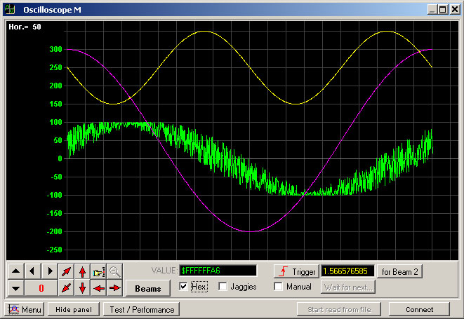
Note: I will not be discussing how this code works because this is a LaunchPad blog and not a C# blog. I am posting this code for those who already know C# or would like to change bits of the source code for their own projects. Keep in mind, this software is far from a polished program, I am using this for my own personal projects and wanted to share it with all of you.
The Code
Setting up the ADC and the Sample Rate
What will look the most unfamiliar to someone who has followed my blog up till this point is the streaming ADC function Start_Stream(unsigned int chan), here I set all the necessary values for the ADC stream. There should be only two lines which are unfamiliar to you which I used in this function.
ADC10CTL0 = ADC10ON + ADC10SHT_3 + MSC+ ADC10IE;
ADC10CTL1 = ADC10SSEL_3 + chan + ADC10DIV_7 + CONSEQ_2;
The first line will, turn on the ADC, set the sample and hold time to 64 clock cycles (which can be thought of as yet another divider for the ADC sample rate), sets the device to do multiple samples and conversions, and finally enables the interrupt. The second line selects which clock to use (the SMCLK), sets the channel to use (which is the ‘chan’ input from the function), sets the clock divider to SMCLK/8, and finally tells the ADC to sample a single channel consecutively.
As I already mentioned, it is important to make sure the sampling rate is low enough for the application UART to send every sample to the PC. Using my code the speed test on my application showed 6.21 kbps. Due to the fact that we are using an ADC that has a 10 bit vertical resolutions, we will need to send every sample as two bytes thus sending 16 bits of data per sample. So to calculate our max sample rate (which we should be a bit under just in case), we divide our data rate by our bits needing to be sent per sample, 6.21kbps / 16 bits = 397.44 Hz.
EDIT (01-26-2012): I would like to correct a mistake that was found in the following paragraph by one of my readers. The problem is with the calculated sample rate. Instead of the equation being SMCLK/8/64/13, it should be SMCLK/8/(64+13). This is because the sample and hold time and the conversion time add together, determining the number of clock samples needed per conversion. This gives us a sample rate of approximately 1.6kHz, a value significantly greater than it should be. That being said, the code will still function, the reasons behind this is a bit complicated and won't be discussed here. Just know that some samples are being dropped and the actual transmission rate is closer to ~450 samples per second. Expect to see a new post in the future with updated code. Sorry for the error!
Our sample rate as set it in the Start_Stream() function is SMCLK/8/64/13. The 8 comes from the clock divider, the 64 comes from the sample and hold time, and the 13 comes from the number of clock cycles it takes to do an actual conversion. This value can be found in the datasheet on page 32 under “10-bit ADC, timing parameters -- MSP430G2x31 only”. SMCLK = 1000kHz (1MHz), so our sample rate is 1000/8/64/13 = 0.150kHz or 150Hz. This is much less than half of our maximum, so we are well within the limit of safety.
Find just the install for the application here. (Note: No promises that this will work for you)
I have decided to post the source code for my computer application since I know how useful it might be to many of you. The reason I was hesitant to post the code is because I do not document and comment my C# code as well as I do my MSP430 code. For anyone who downloads and uses my C# application, please do not expect well documented and commented code, though I will do my best to answer your questions on the 43oh.com/forum. Also, as with all of my code I ask anyone who uses it to mention in the code and anywhere it may be published or posted to site my blog and give me credit for whatever I have written. This includes the software UART and any other functions which I have specifically written.
The computer application looks the same as the one I posted previously, except now the streaming buttons are not greyed out. The main difference is the oscilloscope code which will display a waveform in real time on the screen quite beautifully. Back when I needed this code for my own project I was writing my own library for displaying the waveform but was never happy with the results. I found this DAQ32datalogger project online which utilized Berstein's library for real time waveform displays. The first link was for a research project testing the use of multiple accelerometers for replacing gyroscopes in real world applications. I was very impressed with his code and really recommend that you all take a look at his YouTube video which he links to on his site. The project utilized 32 accelerometer channels and displays all of them in real time on his PC. I emailed the author a few months ago and he is happy that his code is being utilized by others. If you use this code, PLEASE give credit where credit is due, his and Berstein's code is amazingly useful and helpful.
It is important to note that this library has much more potential and can do so much more than I use it for here. Eventually I plan on using this code for monitoring multiple bio-potential signals in real time. The image below is taken from Berstein’s website.
Note: I will not be discussing how this code works because this is a LaunchPad blog and not a C# blog. I am posting this code for those who already know C# or would like to change bits of the source code for their own projects. Keep in mind, this software is far from a polished program, I am using this for my own personal projects and wanted to share it with all of you.
The Code
Setting up the ADC and the Sample Rate
What will look the most unfamiliar to someone who has followed my blog up till this point is the streaming ADC function Start_Stream(unsigned int chan), here I set all the necessary values for the ADC stream. There should be only two lines which are unfamiliar to you which I used in this function.
ADC10CTL0 = ADC10ON + ADC10SHT_3 + MSC+ ADC10IE;
ADC10CTL1 = ADC10SSEL_3 + chan + ADC10DIV_7 + CONSEQ_2;
The first line will, turn on the ADC, set the sample and hold time to 64 clock cycles (which can be thought of as yet another divider for the ADC sample rate), sets the device to do multiple samples and conversions, and finally enables the interrupt. The second line selects which clock to use (the SMCLK), sets the channel to use (which is the ‘chan’ input from the function), sets the clock divider to SMCLK/8, and finally tells the ADC to sample a single channel consecutively.
As I already mentioned, it is important to make sure the sampling rate is low enough for the application UART to send every sample to the PC. Using my code the speed test on my application showed 6.21 kbps. Due to the fact that we are using an ADC that has a 10 bit vertical resolutions, we will need to send every sample as two bytes thus sending 16 bits of data per sample. So to calculate our max sample rate (which we should be a bit under just in case), we divide our data rate by our bits needing to be sent per sample, 6.21kbps / 16 bits = 397.44 Hz.
EDIT (01-26-2012): I would like to correct a mistake that was found in the following paragraph by one of my readers. The problem is with the calculated sample rate. Instead of the equation being SMCLK/8/64/13, it should be SMCLK/8/(64+13). This is because the sample and hold time and the conversion time add together, determining the number of clock samples needed per conversion. This gives us a sample rate of approximately 1.6kHz, a value significantly greater than it should be. That being said, the code will still function, the reasons behind this is a bit complicated and won't be discussed here. Just know that some samples are being dropped and the actual transmission rate is closer to ~450 samples per second. Expect to see a new post in the future with updated code. Sorry for the error!
Our sample rate as set it in the Start_Stream() function is SMCLK/8/64/13. The 8 comes from the clock divider, the 64 comes from the sample and hold time, and the 13 comes from the number of clock cycles it takes to do an actual conversion. This value can be found in the datasheet on page 32 under “10-bit ADC, timing parameters -- MSP430G2x31 only”. SMCLK = 1000kHz (1MHz), so our sample rate is 1000/8/64/13 = 0.150kHz or 150Hz. This is much less than half of our maximum, so we are well within the limit of safety.
ADC10CTL0 &= ~ENC;
ADC10CTL0 &= ~ADC10SC;
ADC10CTL0 &= ~ADC10ON;
These three lines of code are what make up the Stop_Stream() function. It is important to note that ENC needs to be cleared first before any of the other values in ADC10CTL0 can be written. Once that is cleared, the conversion is stopped and the ADC is turned off to save power.
Why Have Commands?
Why not just make the chip constantly send out the data stream of the analog channel conversion results? All we want is an oscilloscope, so why need all of these weird command things? First, if you wanted to do that you would not use an MSP430 but rather you would use a nice and cheap ADC that has a UART out. We also have a built in temperature sensor, and internal VCC measurements which allow us to know almost exactly what voltage is being read by the ADC. Second, it is much easier to interface with a computer application when the program has control over the data flow. Without these commands the application would have a hard time making sure all the data is being received correctly and would not be able to read any of these other nice values the MSP430 can provide.
Improving the Design
The biggest improvement which I’m sure everyone would like to see is an increase in sampling speed. I will not be doing a post on a faster scope design because it should be very easy to scale this code to faster speeds. If you decide to use an FTDI chip instead of the application UART you can recalculate the maximum speed the software UART can transmit at, then reconfigure the ADC to sample at a certain speed using the method I used in this post. If you would like to use an MSP430F5528 to increase speed, send me an email and I can send you the original source code this project was build from.
Final Thoughts
I hope you all enjoyed this series and find the LaunchScope useful. I have been and will be very busy in the upcoming months since I am leading a “Senior Design” project for my university. The project does utilize multiple MSP430s and I will be doing my best to post more guides on topics which come up during the course of my work.
Before I finish I have an unrelated question for any of my readers which might have experience with Actel FPGAs. I am thinking of using an Actel FPGA for a project and was wondering if anyone has had any experience with Actel FPGAs. I have only used Xilinx and Altera but saw that Actel has very cheap and low powered FPGAs. Any opinion on Actel chips would be greatly appreciated. Email me, webmaster@msp430launchpad.com.
Again, sorry for the delay, but I hope the wait was worth it. When I get around to it, the next post will discuss communication between two (maybe three) LaunchPads using I2C. If you have any simple questions about the post feel free to comment and I will do my best to answer any questions. If you have a complex question or would like some help with your code check out 43oh.com/forum, they have a great forum which I check when I can.
Why Have Commands?
Why not just make the chip constantly send out the data stream of the analog channel conversion results? All we want is an oscilloscope, so why need all of these weird command things? First, if you wanted to do that you would not use an MSP430 but rather you would use a nice and cheap ADC that has a UART out. We also have a built in temperature sensor, and internal VCC measurements which allow us to know almost exactly what voltage is being read by the ADC. Second, it is much easier to interface with a computer application when the program has control over the data flow. Without these commands the application would have a hard time making sure all the data is being received correctly and would not be able to read any of these other nice values the MSP430 can provide.
Improving the Design
The biggest improvement which I’m sure everyone would like to see is an increase in sampling speed. I will not be doing a post on a faster scope design because it should be very easy to scale this code to faster speeds. If you decide to use an FTDI chip instead of the application UART you can recalculate the maximum speed the software UART can transmit at, then reconfigure the ADC to sample at a certain speed using the method I used in this post. If you would like to use an MSP430F5528 to increase speed, send me an email and I can send you the original source code this project was build from.
Final Thoughts
I hope you all enjoyed this series and find the LaunchScope useful. I have been and will be very busy in the upcoming months since I am leading a “Senior Design” project for my university. The project does utilize multiple MSP430s and I will be doing my best to post more guides on topics which come up during the course of my work.
Before I finish I have an unrelated question for any of my readers which might have experience with Actel FPGAs. I am thinking of using an Actel FPGA for a project and was wondering if anyone has had any experience with Actel FPGAs. I have only used Xilinx and Altera but saw that Actel has very cheap and low powered FPGAs. Any opinion on Actel chips would be greatly appreciated. Email me, webmaster@msp430launchpad.com.
Again, sorry for the delay, but I hope the wait was worth it. When I get around to it, the next post will discuss communication between two (maybe three) LaunchPads using I2C. If you have any simple questions about the post feel free to comment and I will do my best to answer any questions. If you have a complex question or would like some help with your code check out 43oh.com/forum, they have a great forum which I check when I can.
As always, comment away! Let me know what you think of the project. If you used the LaunchScope or the code from this series for anything cool, post a comment about it. Stay tuned, I will be writing more posts.
Tuesday, September 14, 2010
A Simple ADC Example on the LaunchPad
I finally have had the time to write up this post. Hopefully in a few more weeks I will have more time and can keep up a steady stream of posts like I was doing before.
As promised in the last post, this post will discuss the basics of the ADC10 peripheral in the G2231 which comes with the LaunchPad. The code will allow the microcomputer to accept simple ASCII commands sent over the LaunchPad's UART from a computer, and act on those commands. Four commands are implemented for this post; there will be two more in the next post which will add streaming functionality to the code.
The Functionality
The first command tests the overall data throughput we can achieve with the microcomputer. I think this is very important since it allows us to see how well our device is performing, and allows us to determine how fast the ADC should sample in real time. The second command uses a built in voltage divider to measure VCC in relation to an internal reference. The third command measures the internal temperature sensor in relation to a different internal reference. The final command measures the voltage on an external pin, in this case A3 in relation to VCC. Note that this code does not continually sample the ADC channels but will only sample once per command. The next post will discuss continuous sampling of a single channel, which will allow us to build a simple (slow) oscilloscope using only the LaunchPad.
Computer Application
To accompany the code on the MSP430 I have written a simple computer application using C# which will allow us to easily interface with the device so we do not have to play around with terminal programs. If any of your projects require a computer interface I highly recommend writing a custom application, I really hate fiddling around with terminal programs.
Note: It seems that there are some problems with the installer. I have not figured out what causes the application to work on some computers and not on others. Hopefully it is just my laptop that is having trouble. I recommend having the .NET 4.0 framework installed, even though I wrote the program for 3.5.
The software allows you to connect to any COM port at any baud rate. The baud rate for this post will be 9600, considering that is the maximum of the LaunchPad, but can be changed if you want to use something like an FTDI chip. Make sure that your LaunchPad is plugged in and the VCP is ready before you run the software, the program does not constantly check which ports are available.

The GUI is pretty self explanatory; if you have any questions, bug reports, or suggestions feel free to post. There is also some additional functionality built into the program which is currently disabled; I will provide a second version of the code for the next post when we start streaming data.
The Code
As always the code is available as a gist at http://gist.github.com/593606. If anyone knows how to force the embedded code to show a vertical scroll bar please let me know.
Going Through the Code
Most of this code builds off of previous posts so I will not be going over it in great detail. To read more about the UART please see the previous post. The code is broken down into multiple functions to increase readability. Receive(); is called when the main loop receives a new value from the software UART. This is not necessary, and might actually reduce the efficiency slightly since every function call requires an extra few assembly commands, but in my opinion it’s worth it since the code is more readable and much easier to modify.
After initializing all the registers the device goes into its main loop. So far the ADC is not initialized, only the software UART is set up. The main loop will determine which command was sent and then calls the necessary functions; the loop will also send any converted ADC values out using the software UART. As is true with most of the code I post, the chip goes into LPM0 when there is nothing to do. Before the CPU goes into low power mode it makes sure there are no flags waiting; this keeps the CPU from missing any events. If this was not done it is possible that a second event would be missed, since the CPU was enabled while it was currently in a loop.
The Receive() function will initiate different tasks depending on which command was sent to the computer. The first command which is handled is used to test the speed at which the UART can send data. It will send 256 values, from 0x0000 to 0x00FF, as fast as it can; this data will be received by the computer application and is tested for errors; if there are no errors the speed of the transmission is displayed. It is important to note that 512 bytes are sent total because each value is a 16 bit word. This was chosen for two reasons. First, the MSP430 is a 16 bit processor; second the ADC measurement can not fit in one byte. The next three commands measure an external analog channel (A3), the temperature, and VCC.
About the ADC
I will not be going into how ADCs work, but I will provide some basic theory pertaining to the one in the G2231. The G2231 has a 10 bit ADC and a multitude of channels available to be measured. A few of these channels are internal. They provide access to an integrated temperature sensor, a zero level calibration channel, and a VCC measurement channel.
First things first, the ADC is not some magical device that instantly determines the amplitude of a signal, the ADC conversion takes a certain number of clock cycles and has a limited sample rate determined by this number. Since we are using the LaunchPad's UART for this project, we are limited by the speed at which we can send the values to the computer and not the maximum sample rate. This post will not deal with consecutive measurements from the ADC, so speed is not a problem yet.
The last important theoretical topic I think is important to understand when using an ADC, is the reference voltage. In the ADC world, reference voltages are done differently for different types of converters. For example, what I am about to say does not pertain to the SD16 is the ADC in the F2013. I will probably make a future post about the SD16.
All ADCs need to have a voltage reference which the input voltage can be compared to. There not only is an upper voltage level which the signal is reference to, but also lower level voltage. For the ADC10, you can use the following as references.
- VCC (upper)
- VSS (lower)
- VEREF- (lower)
- VEREF+ (upper)
- VREF- (lower)
- VREF+ (upper)
There are two voltages which can be generated in the G2231, the 1.5V and the 2.5V reference. For this example we will use both the 1.5V and the 2.5V references, in addition to VCC, for all cases VSS will be used as the lower voltage reference.
The Two ADC Functions
The most basic of the ADC measurement functions, is the Single_Measure(chan) function. This does not use any internal references and will measure the channel 'chan' only once.
ADC10CTL0 &= ~ENC; // Disable ADC
ADC10CTL0 = ADC10SHT_3 + ADC10ON + ADC10IE; // 16 clock ticks, ADC On, enable ADC interrupt
ADC10CTL1 = ADC10SSEL_3 + chan; // Set 'chan', SMCLK
ADC10CTL0 |= ENC + ADC10SC; // Enable and start conversion
The first line is important since this might not be the first time the ADC is setup. Most values in CTL0 cannot be changed until the ENC bit is cleared; this is done to prevent unintentional parameter changes. Since this starts a single conversion we do not need to worry about setting up the timing correctly; I did not want to go into too much detail about this until the next post.
The next line determines how many clock cycles there are per conversion, turns on the ADC, and enables the ADC interrupt. Turning on and off the ADC10 is very important since the ADC will draw power as long as it is turned on. It is good programming practice to turn the device off when you are not using it.
The last two lines set the clock source, the ADC channel, and then start the ADC. This example uses the SMCLK and sets the channel to what was defined by ‘chan’. In order for the ADC to be started both the ENC and ADC10SC bits need to be set. See the Receive() function for how to call this ADC function.
Single_Measure_REF(chan, ref) is the second ADC function in this code. Like the first function this will only read one ADC value; the difference is that this function allows us to use one of the two internal references. See the Receive() function for how this function is used.
Other than the delay, there is only one different line between the first and the second ADC functions. TI recommends using a small delay after turning on an internal voltage reference to allow time for the voltage to settle; thus the small delay. Note: This only needs to be done when the reference is turned on.
ADC10CTL0 = SREF_1 + ADC10SHT_3 + REFON + ADC10ON + ref + ADC10IE;
This line of code does 3 things which the last function did not do. In addition to enabling the internal reference and setting whether the 2.5V or 1.5V reference is used, it specifies how the ADC uses these references. This line of code sets the ADC to use SREF_1, which uses VREF+ and VSS for upper and lower references respectively.
The Rest of the Code
The only other part of the code which you might not recognize is the ADC interrupt function. This function will let the main loop know that an ADC value is ready to be transmitted. The transmission is not done directly in the interrupt because one should minimize the amount of code which is present in interrupt routines. This is important since problems can arise when a new interrupt is thrown and the last interrupt has not finished executing yet.
Conclusion
I have decided to not include the source code for the application in this post, but I will be providing it for the next. For now the application is available as an installer only. See the readme provided with the application for a bit more information on how to use it and uninstall the program. If anyone knows how to release a truly standalone .exe using Visual Studio 2010, please let me know since I don’t like installers.
I hope that you find this code useful and are not too disappointed that I have not provided the code for continuous measurement just yet. The code is done, and I just need to test a few more things and write up the next post.
So if you have any questions, or feedback, please comment away. I feel as if this post is not as nicely written as my others, so if there is anything that is not clear please let me know.
Hope you enjoy the code and mini application!
Tuesday, August 17, 2010
Half Duplex Software UART on the LaunchPad
Before I get into this post, I want to let you all know that the very basic oscilloscope project is coming; this post is the first in a series which will lead up to the final project. Before you all get too excited though, the scope will be very limited because of the low sample rate we must have. Be prepared to see some cool mini-projects as we work toward our main goal. This blog and the ones which follow, mirror what I have done with the F5528 for my own personal project.
This post is fairly short; this is due to the fact that I will break down the larger project into smaller posts to keep things bite sized and allow you to follow my design process. I think it is very important to learn how to develop in steps when working with a complex design; there are many benefits to doing things this way.
A Part of the Big Picture
Making a software UART which can receive was a clear first step in making sure we can get an ADC to work. In order to see what we are getting with the ADC we need a computer interface, and in order to control the LaunchPad we needed to be able to receive data. In addition to using this in our oscilloscope project, there has been a lot of interest in the community for a software UART which can receive.
Before we go onto looking at the code, I want to discuss the limitations of this specific software UART. I have not tested the overall throughput to see how fast it can go, as such, there will be a lower limit on the bit times regardless of clock speed. Clock speed can be used though to make the whole system run faster. Before we finish the scope project we will be running at 8 or 16 MHz, and sending data over an FTDI chip much faster than the LaunchPads debugging UART allows. For now though I want to keep the baby steps to something everyone can do (with or without the FTDI chip).
Another major limitation of this code is that it can not receiving while sending, and it can not send while receiving. It IS possible to write a software UART which is full duplex, though I will not be designing one; at least for the foreseeable future.
A Part of the Big Picture
Making a software UART which can receive was a clear first step in making sure we can get an ADC to work. In order to see what we are getting with the ADC we need a computer interface, and in order to control the LaunchPad we needed to be able to receive data. In addition to using this in our oscilloscope project, there has been a lot of interest in the community for a software UART which can receive.
Before we go onto looking at the code, I want to discuss the limitations of this specific software UART. I have not tested the overall throughput to see how fast it can go, as such, there will be a lower limit on the bit times regardless of clock speed. Clock speed can be used though to make the whole system run faster. Before we finish the scope project we will be running at 8 or 16 MHz, and sending data over an FTDI chip much faster than the LaunchPads debugging UART allows. For now though I want to keep the baby steps to something everyone can do (with or without the FTDI chip).
Another major limitation of this code is that it can not receiving while sending, and it can not send while receiving. It IS possible to write a software UART which is full duplex, though I will not be designing one; at least for the foreseeable future.
The Code
The code is posted on github at http://gist.github.com/532047 for those of you who have trouble seeing the embedded code here. I just love github, I do not know what I would do without it.
The code is posted on github at http://gist.github.com/532047 for those of you who have trouble seeing the embedded code here. I just love github, I do not know what I would do without it.
A Quick Explanation of the Code
The code is decently documented, and you all should be familiar with the transmit part of the code; if you aren't, please see this past post where I go over the transmit functionality. I will not really go into detail on all the specific lines of code but I will discuss how the receive code works.
For every byte that is sent over UART there is a start bit which always moves the signal from high to low. Our code recognizes this by throwing an interrupt on the RXD pin when a signal goes from high to low. It is important to disable this once the receive sequence is started, and it is also just as important to re-enable the interrupt once we are done receiving a byte. Once the interrupt is thrown, the timer and other values are initialized.
Next, the timer interrupt cycles through each bit in a very similar way the transmit function does. The major difference between the two is that instead of shifting the bits out, it reads the RXD pin and sets a bit in the RXByte. This is a bit hard to understand if you have not seen this method being used before. The current bit being read will set or leave cleared the 13th bit in RXByte; the entire byte is then immediately shifted once in order to slowly move the bits into the correct location. After an entire sequence is done all the bits will end up in the correct location.
Finally the stop bit is read, and the timer finishes up. It not only stops the timer and re-enable the interrupt on the RXD pin so we can receive another byte, but it also makes sure the start and stop bits are correct values. If an incorrect value has been received for these bits, the received value is ignored.
The final tricky part of this code, is understanding how the main loop knows a value has been received and how the low power modes work. It wouldn't be an MSP430 project if there wasn't some form of power saving going on :-P.
The main loop will go to sleep every iteration unless there is a value which has just been received, in which case the loop will run again. In the timer code, if the received byte is validated and shown to have no errors, it not only sets the hasReceived flag but also forces the CPU to leave the low power mode, which lets the main loop run and react to the received value.
Conclusions
As always, I hope that this code is something that helps with your projects and is peaks your interest in what is to come.
On a separate note, I am very happy to see the community growing. I have had an increase in viewers and I see more activity on the 43oh forums. I check these forums every few days and do my best to answer any questions, so if you have not joined yet I highly recommend doing so. I also plan on taking a more in depth look at the LaunchPad wiki Learning Community that a TI employee started up a bit ago. There seems to be a good amount of information already present on the site, and there also seems to be a huge potential for growth. I really am grateful to TI for providing us all with support and a large number of resources to get the community going.
So, comment away. Your comments are the fuel which my creative juices run on :-P
IMPORTANT EDIT: There is a small error in the code I presented above. The transmit function is problematic because if you send two bytes in a row the TXByte value would be changed before it is done being transmitted. For now I will write in a quick fix, in the next post I will provide a slightly more efficient solution. The code is updated above.
IMPORTANT EDIT: There is a small error in the code I presented above. The transmit function is problematic because if you send two bytes in a row the TXByte value would be changed before it is done being transmitted. For now I will write in a quick fix, in the next post I will provide a slightly more efficient solution. The code is updated above.
Thursday, August 12, 2010
Yet Another Update Post
Before I continue with any fun code examples and projects I want to say my thoughts pertaining to my last post, about the shield standard. I also want to outline where I see the next few posts going and hopefully get some feedback from you guys.
The New Domain
I'm sure some of you noticed the new domain name! We are now officially www.MSP430LaunchPad.com! I hope this can help with the growth of the community and the blog, I also hope this will give me more flexibility in uploading non-blog pages and maybe even hosting some simple projects. This is why I put up advertisements a bit ago; initially I wanted my blog free of them, but I realized with ads after enough time goes by I can use the money to do some cool things. If there is enough revenue from them, I will use the money to fund contests or events, where LaunchPads or shields I design are given away.
The Shield Standard
To be blunt, I am not too proud of my last post. I would need to put in more time than I am willing to put in to write up a really good standard. The last post was more to get my idea's out there, such as the idea of a BaseBoard and LaunchStack. One thing I want to be sure of is that there is a way to use the more powerful processors with the LaunchPad and with whatever shields may be sold. This in itself would help bring about the success of the LaunchPad. That being said, I hope that I didn't disappoint you all too much with such a lacking proposal; if anyone wants to take up where I left off go for it. I will support any idea as long as I can be convinced it is viable and useful.
Upcoming Posts
The next few posts will cumulate in an oscilloscope built using the LaunchPad. There are a few problems with this, first being the 9600 baud rate supported by the LaunchPad will allow only 480sps. This means the final result will use an FTDI chip to communicate over USB. I still haven't decided how I want to do this, and in which order. I think the first test code will send an ADC reading when a button is pressed. The second will use a full duplex software UART to interface will a program I will write, which will replace the push button. I might even sample at a higher rate for a predetermined period of time (set by the program) in order to register full waveforms. We shall see. I would like to create a fully functional (slow ~ 100ksps) oscilloscope with some custom software to interface with it, but a few problems remain to be solved. I would eventually want to build a LaunchPad oscilloscope kit which I would sell.
LaunchPad Board Store
I think that there is enough of a market to start selling development boards. There are a few logistical problems with this though. The first is that I would require people to pre-order boards, and after a certain amount of time goes by or the minimum number of orders are made, I would get the boards manufactured the get them shipped out with all the components one would need. At first I would have 2 or 3 different types of boards. Any profit I would make would be put back into the store in order to provide more boards or to eliminate the need for pre-ordering boards. Prices could even go down if there is enough interest, the more boards being sold the cheaper they would be for me to get manufactured. If I can end up setting this up, you can expect another much more detailed post about it.
Keep in mind, we are now MSP430LaunchPad.com
:-)
Keep the comments flowing.
The New Domain
I'm sure some of you noticed the new domain name! We are now officially www.MSP430LaunchPad.com! I hope this can help with the growth of the community and the blog, I also hope this will give me more flexibility in uploading non-blog pages and maybe even hosting some simple projects. This is why I put up advertisements a bit ago; initially I wanted my blog free of them, but I realized with ads after enough time goes by I can use the money to do some cool things. If there is enough revenue from them, I will use the money to fund contests or events, where LaunchPads or shields I design are given away.
The Shield Standard
To be blunt, I am not too proud of my last post. I would need to put in more time than I am willing to put in to write up a really good standard. The last post was more to get my idea's out there, such as the idea of a BaseBoard and LaunchStack. One thing I want to be sure of is that there is a way to use the more powerful processors with the LaunchPad and with whatever shields may be sold. This in itself would help bring about the success of the LaunchPad. That being said, I hope that I didn't disappoint you all too much with such a lacking proposal; if anyone wants to take up where I left off go for it. I will support any idea as long as I can be convinced it is viable and useful.
Upcoming Posts
The next few posts will cumulate in an oscilloscope built using the LaunchPad. There are a few problems with this, first being the 9600 baud rate supported by the LaunchPad will allow only 480sps. This means the final result will use an FTDI chip to communicate over USB. I still haven't decided how I want to do this, and in which order. I think the first test code will send an ADC reading when a button is pressed. The second will use a full duplex software UART to interface will a program I will write, which will replace the push button. I might even sample at a higher rate for a predetermined period of time (set by the program) in order to register full waveforms. We shall see. I would like to create a fully functional (slow ~ 100ksps) oscilloscope with some custom software to interface with it, but a few problems remain to be solved. I would eventually want to build a LaunchPad oscilloscope kit which I would sell.
LaunchPad Board Store
I think that there is enough of a market to start selling development boards. There are a few logistical problems with this though. The first is that I would require people to pre-order boards, and after a certain amount of time goes by or the minimum number of orders are made, I would get the boards manufactured the get them shipped out with all the components one would need. At first I would have 2 or 3 different types of boards. Any profit I would make would be put back into the store in order to provide more boards or to eliminate the need for pre-ordering boards. Prices could even go down if there is enough interest, the more boards being sold the cheaper they would be for me to get manufactured. If I can end up setting this up, you can expect another much more detailed post about it.
Keep in mind, we are now MSP430LaunchPad.com
:-)
Keep the comments flowing.
Subscribe to:
Posts (Atom)