
In this post I will be showing you how to make a new project which uses a button in addition to discussing what makes MSP430's special.
I have decided not to go into depth about the blinking light code since it is very simple and since you will learn more from the code we will be analyzing in this post.
So. What makes the MSP430 special? Power. It draws so little current, that it is basically the industry default for applications that need super low power consumption. This is something that is very useful, and I think the most important part of the MSP430 and it is why I choose to use this controller for my project. Imagine having a data logger that stores temperature every hour that runs off a small battery. Now imagine it lasting 50 years on that one battery. The MSP430 can do this. That being said, there are also so many MSP430 uCs out there that you can succesfully use in a HUGE range of applications.
So this post will be tailored for the beginners who are wondering whats next after blinking an LED? Should you go right to making a webserver? Or cellphone? No. Start with smaller project and progress toward a goal you have made; learn what you need as you go and plan your steps out. If you just got your LED blinking and are already know what your doing, this post might be a bit too "beginner" for you, keep that in mind.
Now onto this posts main topic. One thing I want to be sure to do with this blog is create posts for all types of MSP430 fans; the beginners and the experts, academics and hobbyists. For experts who already have projects, maybe its time to start playing with that MSP430 that you want to use in your project. My next post will be about using other MSP430 micros. I do not think a beginner should move to a new micro till they have a basic understanding of the chip they have. Expect to see a post about the SD16 ADC and aliasing with the 2013 in the future, and also expect to see a post about how the timers and clock systems work in the MSP430.
Change the Code and Program the Device
This post we will be using another test program from "MSP430F20xx, G2x01, G2x11, G2x21, G2x31 Code Examples". See my previous post if you have not yet downloaded this directory. This set of examples is the most useful tool TI will ever be giving you (other than the LaunchPad itself)(and the actual family User Guide). The code can teach you how to use EVERY single peripheral that is integrated into your chip. Notice though that the title shows other chips in addition to the chip the LaunchPad came with, so some of these programs will not work since the 2231 does not have all the peripherals (such as the SD16 ADC I keep talking about).
We will be using the file "msp430x20x3_P1_02.c" which will toggle an LED every button press. This is what the code looks like this before we modify it.
#include "msp430x20x3.h"
void main(void)
{
WDTCTL = WDTPW + WDTHOLD; // Stop watchdog timer
P1DIR |= 0x01; // Set P1.0 to output direction
P1IE |= 0x10; // P1.4 interrupt enabled
P1IES |= 0x10; // P1.4 Hi/lo edge
P1IFG &= ~0x10; // P1.4 IFG cleared
_BIS_SR(LPM4_bits + GIE); // Enter LPM4 w/interrupt
}
// Port 1 interrupt service routine
#pragma vector=PORT1_VECTOR
__interrupt void Port_1(void)
{
P1OUT ^= 0x01; // P1.0 = toggle
P1IFG &= ~0x10; // P1.4 IFG cleared
}
Lets get this up and running first. Open up CCS making sure you have the workspace the same as last time (you don't have to, but I recommend using the same workspace till you start a totally new project).
Click on File -> New -> CCS Project
Name the project ToggleLED, click next.
Select MSP430 as the project type click next.
There are no dependancies on code from other projects, so click next again.
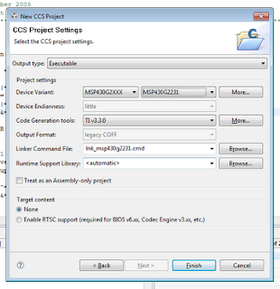
Under Device Variant select MSP430G2231 since this is still the device we are using. Now click Finish.
You can now see your new project set to active in the Project pane. Close out any files that are open then notice the MSP430G2231.ccxml file. This file, was generated automatically during our project setup; it tells the IDE which programmer and which chip we are using.
Right click on the project named "ToggleLED", create a New -> Source File, and name it "main.c". Copy and paste the code I showed above into the new "main.c" file.
Before we program the device we need to change a few lines of code. First change the include file again to "msp430g2231.h"; from now on I will not be mentioning this step or the project setup steps since you should now know how to do it from this post and my previous post. Also, the pin which is used for the button on the LaunchPad is P1.3 which is not the pin used in this code, so we need to change that. The hex value 0x08, or the binary value 0b00001000, is the value which is needed to modifty pin 3 in code. The pins start at 0 and go to 7 on each port.
Change the code to the following (it should be self explanatory which lines get changed):
P1IE |= 0x08; // P1.3 interrupt enabled
P1IES |= 0x08; // P1.3 Hi/lo edge
P1IFG &= ~0x08; // P1.3 IFG cleared
...
P1IFG &= ~0x08; // P1.3 IFG cleared
Now you can program the board; click the little bug and run your code like we did last post. To warn you, the program might be doing some weird things; sometimes when you press the button the light might not toggle, sometimes it will. This problems can be fixed with something caused debouncing. When we talk about timers I might explain how to add debouncing to this code. See the link above for more information.
Explanation of the Code
First the Watchdog Timer (or WDT) is disabled; this is the part of the chip which basically makes sure nothing is wrong or stuck. If there is something wrong with the uC it will reset the chip. See this link for a bit more info. Typically, most programs that you will write will start off by stopping the WDT.
Side Note: The website I linked to for more information about the WDT is a very good website for learning about the MSP430. Browse their tutorials if you get stuck with my simple explanations or want more information. I HIGHLY recommend these tutorials.
Back to the code. The next line sets the first bit in register P1DIR, which is what determines if a pin will be an input or output. This can be done for any of the pins on any of the ports, and must be done before using a port as an output.
P1IE |= 0x08; enables the interrupt for byte 3 in Port. Interrupts are one of the most important concepts to understand when writing code for embedded systems. For those of you with a programming background you can think of it like this: When writing a program that needs to run "indefinitely", you do not want to just write a simple infinite while loop in your main function but you would want to use threads which look for certain things and will then call functions you have defined depending on certain events. Notice how this piece of code does not have an infinite while loop, all it does is set up the chip then go to low power mode. The interrupt on P1.3 will cause the uC to wake up and call the specific function for that event which we have defined in the code. In this case that function is Port_1(). I will discuss this more when I provide an introduction to either the Timers or ADC peripherals.
Then we set how the pin will trigger an interrupt; in this case when P1.3 goes from high to low the interrupt is triggered. Clearing the interrupt flag before interrupts are enabled is very important, in case for some reason one of the bits was set when the device was turned on. One thing about microcomputers is that you can not rely on registers to be initialized 100% correctly. Some registers you can, but some you can't. I for one don't feel like looking through the data sheets to find out for all registers what the defaults are, so I will be coding safely when I supply my own code as long as it doesn't effect things negatively.
The rest of the code is pretty self explanatory; if your having trouble I recommend looking up the things you don't understand in the family User Guide or to look at the tutorials I mentioned above.
Whats Next?
Well, you know how to control LEDs and you know how to register input from buttons; so design something cool and test your knowledge. Start to hook up more LEDs to the board, use more buttons; you should buy a breadboard and some components if you don't have one. If there's enough interest I will write a quick post on prototyping with breadboards and components.
So, what are you going to do next? What kind of projects do you want to build? What are you struggling with? Comment away.
Very cool! I got it to work and now will go back and re-read the article so I know exactly what's going on.
ReplyDeleteI realized just the other day that I can connect this to a breadboard I have lying around. I'm sure everyone else is already aware of this but when I figured it out my mind was blown. I succeeded in controlling an external LED. But what, exactly, is the best way to connect the launchpad to a breadboard? Just solder on the male PCB connectors to use in conjunction with females that connect to the breadboard?
Would cutting off the emulation side of the Launchpad and connecting it to the MSP via breadboard be a bad idea? Seems like it would be convenient, especially if you have several projects with their own MSP, and it would take up less space.
As for future articles/projects, I'd really love to learn how one could use analog inputs/outputs and control servos.
I've noticed that blogger has problems with less-than and greater-than signs. If you use them in include statements (I'm betting you did; I use them too) then they don't translate into blogger directly. They actually create html flags, and so the include line doesn't appear correctly. I learned after some digging that you need to use the html codes < and >, so your line in blogger for the code header should read #include <msp430.h> or similar.
ReplyDeleteBlah.. I had to do some hacking to get blogger to even display the comment properly. Just typing < displays <, so I have to type &lt; to get it to display <
Great post, by the way! I was just debating whether I should do a quick post on buttons before moving on, but I may wait until another time for that since you got this up today.
I was waiting for you to post (since I followed along with your Getting Started post), but I won't have a chance to really read it and experiment until Saturday, unfortunately.
ReplyDeleteKeep up the good work, man, it's a huge help to us newbies. For every person that posts in the comments there are probably two dozen who read it and didn't say anything. So yeah, definitely keep it up. We'll be reading.
@Tim
ReplyDeleteHooking the LaunchPad to the breadboard is a great idea. Make sure that you disconnect the emulator side of the launchpad from the socket side. You now have two options for hooking this up to the breadboard, either connect to the headers that you just took the jumpers off, or use the 6 pin SBW holes on the right side of the board (I mentioned this in a previous post).
Be careful about powering the device while programming it though, I would recommend turning off your external power and using the LaunchPad's power while you are programming till I can write a post about what to look out for and how to do this safely. Also be sure to use a power supply that won't blow your chip.
An ADC post will be incoming after I get a few more LaunchPad specific posts up here. I'm having trouble with code that worked perfectly in the past too. Hmmmm...
@David
Thanks for pointing that out. I'm actually having some frustrations with Blogger's formatting. I do happen to use the " though for include, the < just came from the sample code. :-)
@Anonymous
Thanks! That's the problem with hobby work, sometimes there's no time during the week. :-P
Thanks again for the feedback, it's easy to forget that not everyone posts when you become the author, lol. Best of luck on Sunday!
Hey NJC you might wanna look at this so posting code will be easier and more readable:
ReplyDeletehttp://code.google.com/p/syntaxhighlighter/
Thanks for the link Zunayed! I'm almost done with the next blog on Timers and PWM, and will be using the SyntaxHighlighter for the code. That helped a ton with readability.
ReplyDeleteThanks so much for the tip.
A _HUGE_ thank you for writing these posts. I am new to uCs, and your beginning level posts are perfect for me.
ReplyDeleteIf you don't mind a quick question:
Am I correct that "|=" means 'set bit to one', "&=" means 'set bit to zero', and "^=" means 'toggle bit'?
-Doc
Doc,
ReplyDeleteThank you! To answer your question, yes and no.
|= is a logic OR, which means that yes, it sets any bits to 1 that are specified.
value = 0b10010000;
value |= 0b00001001;
After those two comments, value would be equal to 0b10011001.
&= means logical AND, so it alone does not mean set bit to zero, you need to have a ~ in there, which means logic NOT. To clear a bit, or set it to 0.
^= does mean toggle bit. 0 to 1, and 1 to 0.
Glad your getting into uC! They are awesome and a lot of fun! If you're still having trouble with the &= and ~, look up some basics on Digital Logic; I'm sure there are tons of pages out there that do a good job explaining it.
Good luck!
Thanks for the answer! I did find out the AND/OR/NOT definitions/usages on a tutorial I think you linked to (cnx.org). Binary logic is starting to come back to me!
ReplyDeleteI set up and ran your ToggleLED program, and modified it to use P1.4 for an external button, but I think I'm having trouble due to no debounce, or the pin floating when not pressed. I'm looking into using a pull-down resistor properly, and looking forward to getting into your timers post to work on debounce.
Thanks again!
-Doc
Doc,
ReplyDeleteHaving no debounce isn't the end of the world when you are just getting started, the symptoms are that the LED will not toggle every time you press the button, try to hit the button with conviction and steadily and it should work out all right.
I would guess that a pull-up or pull-down resistor would solve your problems, a switch will not properly work if a pin is left floating. Even in VHDL there is are four levels you can set a pin to; 'low', 'high', 'dontcare', 'highZ'. Having a floating pin is the same as highZ, this shows how important the difference between 0, 1, and a floating pin is.
Also, glad you found use in the tutorial link I posted, I think those tutorials are great. I hope that the resistor will solve your problems :-)
-NJC
I cannot get my PC to communicate with the launchpad. it had the driver installed on hookup to the PC. any help please
ReplyDeleteRich, without more information I can't really help. Please re-post your question on TI's forums (e2e.ti.com), or 43oh.com/forum, or the LaunchPad Google Group. There will be more eyes there ready to help you. Thanks.
ReplyDeleteHey this is great. I'm really enjoying it. Thanks.
ReplyDeleteThank you very much for nice tutorials. A few comments:
ReplyDelete* Change the comments too when changing the sample code. E.g. P1IE |= 0x08; // P1.3 interrupt enabled
* I would like some explanation for the rest of the code. How does the interrupt know to call the function Port_1? Because it is the only interrupt function? What does _BIS_SR do? What about the pragma?
@slackerprime :-) Thanks!
ReplyDelete@Tor
Thank you for the comments. Since this post I've been more careful about keeping my comments as close to perfect as possible. I will go back and edit the post though to eliminate any confusion. Thanks.
I chose not to go into the inner working of the processors in the blog posts, but I can give you a quick answer, and point you to more in depth resources. In the MSP430 there is something called an interrupt vector, this vector points to a certain location in the program memory. Once an interrupt happens, the program jumps to the interrupt routine. This is marked in c code by the #pragma vector=PORT1_VECTOR. PORT1_VECTOR is a constant which is defined in the header files. #pragma is what CCS uses, I know GCC uses something different, so please be aware of that in case you are not using CCS.
The best place to learn about how the MSP430 functions on the lowest level is the Family User Guide. It really has all the information you need to understand all aspects of the processor. I also would recommend learning ASM if you want to have a deep understanding of how the processor works. If you have any other in depth questions, head over to 43oh.com/forum and I will be sure to answer them within a few days. :-) Hope that explanation answered your questions.
Thanks for the answer! I've been making some fun little things with the Launchpad, though I realize I have a lot to learn about micro-controllers. My current problem is how to make the timer interrupt happen when in low power mode. I'm sure it's in the user guide somewhere though.
ReplyDeleteThank you so much for these tutorials! They are a great help!
ReplyDelete@Tor
ReplyDeleteCheck out the following blog post: http://mspsci.blogspot.com/2010/07/tutorial-08-beating-heart-bcs-part-i.html
My best guess is that you are having trouble with clocks being turned off in low power mode. Depending on which mode you are in, certain clocks are turned off and if the clock which feeds the timer is off there will be no timer interrupt.
@Jeffrey - Glad I can help! :-)
Fantastic! Thanks for the tutorials. I am in the process of transitioning from the BasicATOM to the MSP430 line, and have been running in to walls in regards to the differences in programming. The step by step code explanation is VERY helpful.
ReplyDeleteThanks so much for these posts. Certainly a treat for new-comers. I've been toying around with interrupts (having never used them before) and the p1.3 button, and my code is trying to call two differnt sub routines with the same button (ie p1.3). So i implemented a simple counter, and on the first interrupt routine, it turns both leds on and return to main{} in LPM4. The second time the button is pressed, it turns off the leds and returns to main{} in a powered up state (~LPMn). THe problem is that the second time the button is pressed it enteres main in LPM anyway! Can't figure it out. any ideas??
ReplyDeleteand really, thanks again for this blog, its great.
@JD, have you tried posting the question on 43oh.com/forums? If you can post the code on the forums, I can take a look at it and try to give you some constructive advice. It is possible that the LPM bit is not getting set correctly in the interrupt, or that you are instantly going to LPM in the main loop.
ReplyDelete@NJC, thanks for the follow-up. I had never heard of 43oh before, looking forward to reading through the forums. As to the problem with the code, i figured out what I was doing wrong. I was using the _bs command in the interrupt instead of the _bs_on_exit command. Though, interestingly enough, once I changed this my code stopped compiling. It took me a long time to figure out that it appears to be a memory problem. Once I deleted some unnecessary header files (which were remnants of other experimental code) it compiled just fine.
ReplyDeleteAny thoughts on this? is this a limitation of the free Code Composer Studio, or the chip itself? The code itself is not very complicated or lengthy...
Thanks again.
i know 0x stands for hex but isn't 0x08 8 in hex not 3 i don;t undeerstand
ReplyDeleteis it that 0x08 is 00001000 and the one is 4th from the righ
Correct me if I'm wrong everyone:
ReplyDeleteP1 is the name of ur input/outputs and it has 8 channels, labeled 0-7, as in P1.0, P1.1, P1.2, etc.
think of it as an 8 bit address, where each bit can be set as a 1 or a 0. So when you say something like P1Dir=0, P1Dir is set to 00000000.
So if you want to toggle the input/output (the direction) of P1.3 then you would have to set it to 00001000 (remember they are numbered from 0) which is the same in hex as 0x08, or decimal 8. And if you want to set P1.0 the call is P1Dir=1 or P1Dir=0x01.
To keep things pretty I have been using the processor definitions (in the MSP***** header file) BIT0-BIT7, where BIT0=0x01, BIT1=0x02, etc
So if you write P1Dir=Bit3 this is equivalent to P1Dir=0x08. This way you can quickly look at it and know that P1.3 is set to '1'
@JD - As far as limitations on code size go, the MSP430G2231 and CCS both have the same memory limitations. CCS (the free version) has a code size limit. You can tell how large your code was by debugging, then after the debug session is started before you hit "run" you can see the code size output in the command line of CCS.
ReplyDeleteAlso, very good answer and explanation for Anonymous's question. Thanks! :-)
Hello
ReplyDeleteThis is a great tutorial! Thank you for this.
But I have a major problem. After following the tutorial, I noticed that the red LED on my launchpad would blink randomly, and sometimes even stay on. I also noticed that when I touch the pin of port 1.3 and vcc at the same time, the LED starts behaving properly. Can you tell me what I should do to avoid this?
Thanks
Hi:
ReplyDeleteHow can I make a pin like P1.1 or P1.2 toggle between float(high-z) and 0(ground)?
@aeozyalcin - What program do you have loaded onto the LaunchPad?
ReplyDelete@Amal - Why do you want to make a pin float? I see no practical reason to do this. Plus, digital I/O pins are not meant to be high-z. If you can explain your purpose I will most likely be able to suggest something else.
1 of 30 times my MSP430G2452 is programed normally.
ReplyDeleteElse I can see this message:
>MSP430: Trouble Writing Memory Block at 0xffe4 on Page 0 of Length >0x2: Could not write device memory
>Cannot write to target
Have yoг any ideas? I need help.
i.kyb@ya.ru
for the new version of the launchpad you have to set the internal pullup resistor with
ReplyDeleteP1REN |= 0x08;
otherwise pressing the button will not work.
And P1OUT |= 0x08;
DeleteAccording to the user manual P1OUT decides wheter it should be a pullup or pulldown
I had some problems getting the button to work without setting it as a pullup
I had the same problem on a Launchpad v1.5. The strange thing was that the program worked if I touched with my finger the P1.3 pin but not using the button, until i added this line.
DeleteHi,
ReplyDeleteCan anyone help me in interfacing 4x3 keypad to MSP430 Launchpad.... and the output should be obtained on the 16x2 LCD. I have already interfaced the LCD, but im not sure about keypad. Pls help me in this regard...
thank you