Friday, July 30, 2010

The LaunchPad's Example Project Ripped Open

In this post I present a broken down version of the LaunchPad's example project which only contains the software UART transmit functionality. Note: the code I present can not receive any UART data. The next post will discuss how to use this code with an FTDI breakout board from Spark Fun (which I just received in the mail) for faster communication.

For this post you will need a terminal software. HyperTerminal which comes with Windows will do fine, but I don't like it very much. I use Realterm.

A Little About UART Basics

What is UART? Universal Asynchronous Receiver/Transmitter; UART is a communication protocol. As I already mentioned this post will only implement the transmitter part.

Asynchronous means that the devices which are connected via UART do not need to be synchronized together (aka, share a clock signal). This is very useful and this is the main benefit of using UART compared to other protocols such as SPI or I2C, the downside of this though is that you sacrifice speed when running asynchronously. The UART connection can be either be full duplex, which means the device can transmit and receive at the same time, or half duplex which means the uC can not send and receive as the same time.

The serial port is one implementation of UART and RS-232 was (is) very common. The problem with a serial port on a computer is that the voltages used to transmit the bits are waaaaaay out of the acceptable input range for a typical microcomputer. Why do they do this? They do this to make the transmission more resilient to noise and interference when transmitted over longer distances. If you are hooking your device into something like the image above (from Wikipedia), make sure you have level converters! This is why I like to use USB chips like FTDI's, or the one built into the 5xx. Plus you can achieve faster speeds with those chips than you can with a typical RS-232 interface.

Last bit of theory for UART. UARTs all have some basic properties which can be changed depending on the application. The main property which can be changed is Baud Rate, we will not discuss the others here since it is beyond the scope of this post. Baud Rate directly corresponds to how fast a bite will be transmitted. The larger the baud rate, the faster a byte is sent.

Note: When sending a byte over UART your device needs to send 10 bits total, one start bit and one stop bit in addition to the 8 bit byte.

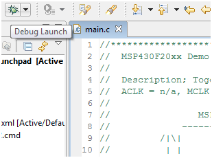
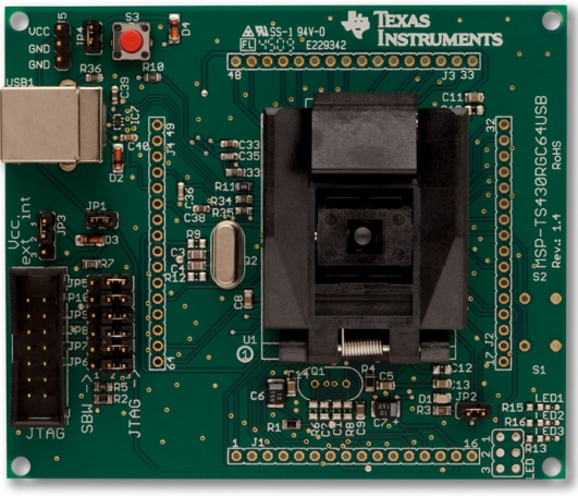
The LaunchPad and Terminal Software

The LaunchPad has the hardware built into the emulator to provide a very slow UART connection to the PC for debugging purposes. It's maximum baud rate is 9600, which I have verified. The drivers that are (hopefully) automatically installed create a virtual COM port (VCP) which a terminal program or any computer application can access. In my case it is COM9, if you don't know which one it is you can check the device manager. If you want faster communication you have to use a seperate USB device. I typicaly have used FTDI chips and will be using an MSP330F5xx chip in the future.

Sorry for all that rambling, here comes the code.

The Code

Code is also posted here. Sorry for the poor comments. Forgot to clean them up before I posted.


About the Code

I will not be going over how I condensed the example project to just contain the UART since that would require explaining how the example project works. I might do that eventually in a separate blog, but not yet. I also changed a bit of their code because there were a few things I really didn't like, or that caused problems; I tried to keep the code as similar as possible to the example code provided by TI. I would have done this a bit differently. I don't claim though that I wrote this code and I state in the comments that I only modified the code. Please keep this in mind. I also don't ever claim that any of my code will ever be perfect, though I will never post code that I haven't tested and validated.

Analysis of the Code

#define Bitime 104 //9600 Baud, SMCLK=1MHz (1MHz/9600)=104

Bitime is the number of clock ticks per bit, in the original code the clock was divided down by 8, and they used a baud rate of 2400; this code uses a baud rate of 9600. (I think they should have called it BitTime).

BCSCTL1 = CALBC1_1MHZ; // Set range
DCOCTL = CALDCO_1MHZ; // SMCLK = DCO = 1MHz

The two lines above set the internal DCO (Digitally Controlled Oscillator) to [almost] exactly 1MHz. The way this works is that CALBC1_1MHZ and CALDCO_1MHZ point to locations in memory that have been written with calibration information that is device specific. Each type of MSP430 will have different values for calibration. I was skeptical about how exact this could be, but after measuring it with my Logic Analyzer, the frequency was almost exactly 1MHz.

P1SEL |= TXD;
P1DIR |= TXD;

These two lines set the mode of the pin selected for TXD. The important thing to note here is that you can not pick a pin that does not have a Timer terminal function. For example P1.5 also can be set to be TA0.0, so you can change TXD to BIT5 and not change any other code. This is because, like in our PWM example, the Timer automatically changes the value of the TA0.0 pin when a CCR0 event happens.

The loop in main should be pretty self explanatory. Make sure you put the value you want to send into TXByte before calling Transmit().

CCTL0 = OUT;
...
CCTL0 = CCIS0 + OUTMOD0 + CCIE; // Set signal, intial value, enable interrupts
...
CCTL0 &= ~ OUTMOD2; // TX Mark`

The three lines above go together, they all handle how the output pin is set. The OUTMODX determines how the signal changes when a CCR0 event happens. We should already be familiar with OUTMOD7 (Set/Reset). When OUTMOD0 is selected, the output signal will be set to whatever value the OUT bit in CCTL0 is set to. The first line above sets this bit to 1, so the output pin will be changed to 1. When OUTMOD2 is set, whenever a CCR0 event happens the output is cleared (set to 0). You can see this in the timer interrupt function, if the bit to be sent is equal to one, OUTMOD0 is set otherwise OUTMOD2 is set. This is a fancy way of saying set the output to 1 when the bit being sent is 1, and set the output to 0 when the bit being sent is 0.

CCR0 = TAR;

The above command sets the compare register to the current value of the timer (TAR). This allows the compare register to start from the correct reference point when additional bitimes are added to the compare register.

I'm now going to explain how it all works and hopefully you can peace things together without me elaborating on every line.

Transmit() is called, this initializes the timer and compare registers, formats the byte to be sent, then starts the timer. Once the interrupt happens, it is time to change the bit. This is done in the interrupt function, which adds the needed offset to the counter first so that the next bit will transition on time even though there is processing being done within the interrupt function. The bit counter is then decremented once each interrupt; this is done until it reaches 0, which means that it is done transmitting the byte which then disables the interrupt. Meanwhile the Transmit() function is still running and is in a loop waiting for the byte to be done. It knows it is done when the timer interrupt is disabled. This loop makes it so that you can't try to send another byte while one is already being sent. Note that this is very wasteful as far as power goes, and that more care should be taken if you are worried about power consumption.

Seeing our Data on the Computer

Go to your terminal program and set the COM port, set the baud rate to 9600, make sure the display is in HEX and reconnect the terminal software to allow the changed parameters to go into effect. Run your code and you should now see values counting upward being sent to the terminal! Cool!

What Next?

Play around with some baud rates and have some fun. If you want to try and use what you've learned so far from previous posts, use the transmit function with a push button interrupt. It's important to see how code pieces together to make cool projects. Use the push button code I mentioned in a previous blog (or a version with debouncing, but this time also transmit a some value (a counter maybe) every button press.

Next post I will be going over how to achieve higher data speeds using FTDI's chip, and the problems I ran into using this code while trying to send data at 115200 baud (the code breaks when bitime is lower then about 50).

As always, comment away. Having any problems? Any cool code modifications you'd like to share? Also feel free to start threads on any of the websites I mentioned in my previous post, I will be watching them.

Have fun!

-NJC

Tuesday, July 27, 2010

A Nice Forum, and a Bone to Pick

A Nice Forum

So I decided to write a little update post on two separate topics. First I found a forum that was posted in the Google LaunchPad Group, and wanted to share it with everyone in case you don't already know of it. If enough people join I think it could be very useful. I will try to be active on both the Google Group and the 43oh.com forum.

http://www.43oh.com/forum/

A Bone to Pick

Second, I have a bone to pick with TI. I will be emailing them about this once I have enough time to word an email correctly. I have just received my 5528 target board, and it is VERY cool. I got home and was super excited to compile the test program and use the Field Firmware Update Demo they speak so highly of in all their documentation. Turns out they DON'T have any firmware update application available.

This frustrates me since this was the real reason I bought the board all together. It is also not a lack of research which caused me to believe the executable was posted. Let me quote one of their documents.

"(NOTE: The starter project will be made available by August 2009. Until then, an executable version of it has been compiled into a demo application, which is available on the MSP430F5529 product folder web page. What follows is a description of what the starter project will be.)"

Generally speaking I trust documents written by a company and do not go out verifiying every little bit of it, I assumed that since they said the executable was posted that it would be. Also, in another document in the same .zip package they show screen shots of the program. Ok, I know, its a "preliminary" document. It was posted over a year ago...

It seems like they are holding out on me. :-( I'm not trying to pick a fight or anything since I am sure they have a good reason to not post it, I am just saying how it seems to me. Hopefully TI will answer my email with a link to the executable instead of their typical answer "Don't worry, you will see it posted in a month or so." This just does not look good from a customers perspective.

Sorry, just needed to vent. I'm done complaining now. I still love TI's hardware products. :-P


Next Post

My next real post is almost done. It will contain a broken down version of the example code which came with the LaunchPad so we can get started using a software UART. I will also do some testing to show how high we can set the baud rate to and have it still be reliable.

I also just wanted to thank everyone who comments on my posts, it really does mean a lot to me to know that I am actually helping people instead of talking (writing?) into thin air.

After the first two weeks of being up and running (it has grown since then too!), I had over 1000 visits to my blog, and about 40 subscribers! Thanks everyone! The more the better! :-)

Thursday, July 22, 2010

Timers and Clocks and PWM! Oh My!

I am going to try and not be so wordy in this post since there is a lot to cover on this topic. I want to do it all at once too; I would rather you have fun code to play with than me do one part of just theory. At the end of this post you will have a PWM library you can use in your projects. So here it goes, let me know what you think.

A clock in embedded electronics is what controls how fast the processor ticks. The MSP430 has multiple clocks which can used for the peripherals and the CPU. MCLK is the master clock for the CPU. SMCLK is the submain clock. Both of these can be selected for use in the peripherals such as an ADC or Timer. I won't discuss ACLK here.

Why so many clocks? Power efficiency. Different clocks are turned off in different low power modes; for example LPM0 disables MCLK and the CPU but leaves SMCLK running so the peripherals hooked up to it can continue to run. These clocks can be generated from a number of different sources and can also be divided down from the clock input. For more information on this see the User Guide.

So. What is all this talk about a silly little Timer? The Timer keeps track of how many clock cycles pass without having to write specific code to keep track of time. This can be useful not only for low power modes, but also for time sensitive projects. To keep it simple and quick, a timer needs to be initialized and enabled. It will then proceed to count as the clock ticks to a predefined value and then start over. You can set the Timer to generate events at multiple times along the way to its end value; these events could be an interrupt when it hits a certain number of clock ticks, or it can toggle, set, or clear a specialized pin. Having the Timer change a pin without calling any interrupts or any specialized code is the best way to create a simple PWM.

What is PWM? Pulse Width Modulation. As far as we are concered, it is a square wave that has a duty cycle at a cetain frequency. Duty cycle is the percentage of time the wave is high across one period. How is it useful? Motor control, light control. Think of an LED, the lower the duty cycle (the less its turned on over a period of time), the dimmer it is. There are countless numbers of applications for using PWM.


More about the Timer

There are a few things you need to know before we start coding. As I said, the Timer counts clock ticks, in reality it can be that simple, but it does not need to be. For example the Timer can count up to a certain number or count up then down. The different functional modes are as follows (directly out of the User Guide).

1. Up Mode - the Timer repeatedly counts from 0 to the value set in register TACCR0
2. Continuous Mode - the Timer repeatedly counts from 0 to 0xFFFF
3. Up-Down Mode - the Timer repeatedly counts from 0 to TACCR0 and back down to 0

The picture above is a visual representation of Continuous mode (taken from the User Guide)

Personally I like Up Mode the best, so we will be using that to build our PWM library. So you can set up an interrupt for when the timer gets to TACCR0 or TACCR1, or you can toggle one of the timer.


The Test Code


Setting up the Timer

First we set up our PWM pins. The code below sets P1.2 to output and enables the pin to be the timer output bit TA0.1.

P1DIR |= BIT2; // P1.2 to output
P1SEL |= BIT2; // P1.2 to TA0.1

Next we have to set up the CCR0 and CCR1 registers, which determine when events happen and how high the clock will count to.

CCR0 = 1000-1; // PWM Period
CCTL1 = OUTMOD_7; // CCR1 reset/set
CCR1 = 250; // CCR1 PWM duty cycle (25%)

Remember, the timer depends on the clock frequency it is running on. So if you have a 1MHz SMCLK and want a PWM frequency output of 100kHz, CCR0 will have to count up to 10 leaving only 9 values for CCR1 to toggle the clock at. This limits the resolution the duty cycle can have. The default DCO (digital controlled oscillator) which is the source of the MCLK and in this case the SMCLK is approximately 1.1MHz, making the PWM frequency about 1.1kHz with a duty cycle of 25%.

Setting CCTL1 = OUTMOD_7 does two things, one of which might not be so apparent. OUTMOD_7 is the Reset/Set option,which means "The output is reset when the timer counts to the TACCRx value. It is set when the timer counts to the TACCR0 value" (From User Guide). This means that when the timer hits CCR0 it starts counting over AND sets the PWM output to 1; this also means that when the timer hits CCR1 it will set the PWM output to 0. See user guide for some nice pictures and explinations.

For this PWM program we will be using SMCLK and Up Mode for the timer. Now we have to set which clock and which mode the Timer is going to use. The following line of code sets the clock and the mode of operation.

TACTL = TASSEL_2 + MC_1; // Chooses SMCLK, and Up Mode.

In this register you can also set the interrupts to be triggered but we will not be doing that here since the PWM pin will be toggled without needing an interrupt.

That is it for the code, hopefully I explained it all throuroughly and efficiently. If you have any question or don't like how I'm writing this post, please let me know. I'm trying less opinion and more fact.


Hooking Up the Hardware

In order to visually see this in action, which I'm guessing a lot of you do, you can use either a Logic Analyzer, or ... an LED. So lets hook up the LED. Since we are limited as to which pins we can hook up to the timer using this method (we can't hook up P1.0), we will need to hook up P1.2 to one of the LEDs on the LaunchPad. I'm hoping that you have installed headers (either male or female) onto the LaunchPad already. Take out the jumper which is above one of the LEDs and then hook the LED to the pin P1.2 on the board. If you are having trouble with this, write a comment, I will help you.

Run the program, then modify away. As you change the duty cycle the LED's brightness will change. The closer CCR1 is set to CCR0, the brighter the LED will be, the farther away the darker it will be. Congratulations, you have tackled PWM and have a basic understanding of the Timer.

In a future post I will be providing libraries for some of the peripherals which you can simply include in your project; this is so you will not have to worry about all the details when using a peripheral. I could just provide those but I think you should understand how it all works before you use it, otherwise you would be programming in C# on a desktop computer. Libraries like I will provide were invaluable to me many years ago when I started with microcomputers.

Hope that was concise and made sense. Give me some feedback if you liked the style of this one better.


Warning: I am attempting to use SyntaxHighlighter for the first time with this post (Thank you for the tip Zunayed!). Please be patient if it takes me a few revisions to get the code displayed correctly (or even at all). Thanks for your patience.

Edit: I just corrected the commenting error in my code which incorrectly said ACLK. Also, below I added an image from my Logic Analyzer verifying the waveform so you guys can see what it looks like. I have P1.0 and P1.2 tied together.


Monday, July 19, 2010

Using Buttons and Creating a New Project

In this post I will be showing you how to make a new project which uses a button in addition to discussing what makes MSP430's special.

I have decided not to go into depth about the blinking light code since it is very simple and since you will learn more from the code we will be analyzing in this post.

So. What makes the MSP430 special? Power. It draws so little current, that it is basically the industry default for applications that need super low power consumption. This is something that is very useful, and I think the most important part of the MSP430 and it is why I choose to use this controller for my project. Imagine having a data logger that stores temperature every hour that runs off a small battery. Now imagine it lasting 50 years on that one battery. The MSP430 can do this. That being said, there are also so many MSP430 uCs out there that you can succesfully use in a HUGE range of applications.

So this post will be tailored for the beginners who are wondering whats next after blinking an LED? Should you go right to making a webserver? Or cellphone? No. Start with smaller project and progress toward a goal you have made; learn what you need as you go and plan your steps out. If you just got your LED blinking and are already know what your doing, this post might be a bit too "beginner" for you, keep that in mind.

Now onto this posts main topic. One thing I want to be sure to do with this blog is create posts for all types of MSP430 fans; the beginners and the experts, academics and hobbyists. For experts who already have projects, maybe its time to start playing with that MSP430 that you want to use in your project. My next post will be about using other MSP430 micros. I do not think a beginner should move to a new micro till they have a basic understanding of the chip they have. Expect to see a post about the SD16 ADC and aliasing with the 2013 in the future, and also expect to see a post about how the timers and clock systems work in the MSP430.


Change the Code and Program the Device

This post we will be using another test program from "MSP430F20xx, G2x01, G2x11, G2x21, G2x31 Code Examples". See my previous post if you have not yet downloaded this directory. This set of examples is the most useful tool TI will ever be giving you (other than the LaunchPad itself)(and the actual family User Guide). The code can teach you how to use EVERY single peripheral that is integrated into your chip. Notice though that the title shows other chips in addition to the chip the LaunchPad came with, so some of these programs will not work since the 2231 does not have all the peripherals (such as the SD16 ADC I keep talking about).

We will be using the file "msp430x20x3_P1_02.c" which will toggle an LED every button press. This is what the code looks like this before we modify it.


#include "msp430x20x3.h"

void main(void)
{
WDTCTL = WDTPW + WDTHOLD; // Stop watchdog timer

P1DIR |= 0x01; // Set P1.0 to output direction
P1IE |= 0x10; // P1.4 interrupt enabled
P1IES |= 0x10; // P1.4 Hi/lo edge
P1IFG &= ~0x10; // P1.4 IFG cleared

_BIS_SR(LPM4_bits + GIE); // Enter LPM4 w/interrupt
}

// Port 1 interrupt service routine
#pragma vector=PORT1_VECTOR
__interrupt void Port_1(void)
{
P1OUT ^= 0x01; // P1.0 = toggle
P1IFG &= ~0x10; // P1.4 IFG cleared
}


Lets get this up and running first. Open up CCS making sure you have the workspace the same as last time (you don't have to, but I recommend using the same workspace till you start a totally new project).

Click on File -> New -> CCS Project

Name the project ToggleLED, click next.

Select MSP430 as the project type click next.

There are no dependancies on code from other projects, so click next again.

Under Device Variant select MSP430G2231 since this is still the device we are using. Now click Finish.

You can now see your new project set to active in the Project pane. Close out any files that are open then notice the MSP430G2231.ccxml file. This file, was generated automatically during our project setup; it tells the IDE which programmer and which chip we are using.

Right click on the project named "ToggleLED", create a New -> Source File, and name it "main.c". Copy and paste the code I showed above into the new "main.c" file.

Before we program the device we need to change a few lines of code. First change the include file again to "msp430g2231.h"; from now on I will not be mentioning this step or the project setup steps since you should now know how to do it from this post and my previous post. Also, the pin which is used for the button on the LaunchPad is P1.3 which is not the pin used in this code, so we need to change that. The hex value 0x08, or the binary value 0b00001000, is the value which is needed to modifty pin 3 in code. The pins start at 0 and go to 7 on each port.

Change the code to the following (it should be self explanatory which lines get changed):


P1IE |= 0x08; // P1.3 interrupt enabled
P1IES |= 0x08; // P1.3 Hi/lo edge
P1IFG &= ~0x08; // P1.3 IFG cleared

...

P1IFG &= ~0x08; // P1.3 IFG cleared

Now you can program the board; click the little bug and run your code like we did last post. To warn you, the program might be doing some weird things; sometimes when you press the button the light might not toggle, sometimes it will. This problems can be fixed with something caused debouncing. When we talk about timers I might explain how to add debouncing to this code. See the link above for more information.


Explanation of the Code

First the Watchdog Timer (or WDT) is disabled; this is the part of the chip which basically makes sure nothing is wrong or stuck. If there is something wrong with the uC it will reset the chip. See this link for a bit more info. Typically, most programs that you will write will start off by stopping the WDT.

Side Note: The website I linked to for more information about the WDT is a very good website for learning about the MSP430. Browse their tutorials if you get stuck with my simple explanations or want more information. I HIGHLY recommend these tutorials.

Back to the code. The next line sets the first bit in register P1DIR, which is what determines if a pin will be an input or output. This can be done for any of the pins on any of the ports, and must be done before using a port as an output.

P1IE |= 0x08; enables the interrupt for byte 3 in Port. Interrupts are one of the most important concepts to understand when writing code for embedded systems. For those of you with a programming background you can think of it like this: When writing a program that needs to run "indefinitely", you do not want to just write a simple infinite while loop in your main function but you would want to use threads which look for certain things and will then call functions you have defined depending on certain events. Notice how this piece of code does not have an infinite while loop, all it does is set up the chip then go to low power mode. The interrupt on P1.3 will cause the uC to wake up and call the specific function for that event which we have defined in the code. In this case that function is Port_1(). I will discuss this more when I provide an introduction to either the Timers or ADC peripherals.

Then we set how the pin will trigger an interrupt; in this case when P1.3 goes from high to low the interrupt is triggered. Clearing the interrupt flag before interrupts are enabled is very important, in case for some reason one of the bits was set when the device was turned on. One thing about microcomputers is that you can not rely on registers to be initialized 100% correctly. Some registers you can, but some you can't. I for one don't feel like looking through the data sheets to find out for all registers what the defaults are, so I will be coding safely when I supply my own code as long as it doesn't effect things negatively.

The rest of the code is pretty self explanatory; if your having trouble I recommend looking up the things you don't understand in the family User Guide or to look at the tutorials I mentioned above.


Whats Next?

Well, you know how to control LEDs and you know how to register input from buttons; so design something cool and test your knowledge. Start to hook up more LEDs to the board, use more buttons; you should buy a breadboard and some components if you don't have one. If there's enough interest I will write a quick post on prototyping with breadboards and components.

So, what are you going to do next? What kind of projects do you want to build? What are you struggling with? Comment away.

Sunday, July 18, 2010

Some News about the LaunchPad

So I have a quick update about the LaunchPad. TI has finally posted the LaunchPad User Guide on their website; oddly enough it is not on the Wiki yet. They also posted a white paper on the LaunchPad but is not really worth the read if you already have your LaunchPad. I do recommend reading the User Guide though, some interesting things in there.

A few quick comments about the LaunchPad. I have verified that you can just plug the MSP430F2013 into the socket on the board and it works perfectly. They also mentioned this in the User Guide. One thing I am not too happy about is that you can not disconnect ground between the programmer and the target side. Not too big of a deal, but I don't like it.

Also, has anyone else been having trouble with the pdf files from TI? I keep getting some weird errors pretty consistently. Its possible its just me though.

Expect a follow up article to my Getting Started Guide soon. I will be discussing the use of the pushbuttons and will explain the code a bit. From this point on the blog will alternate between news, beginner guides, and advanced topics. Feel free to let me know if there is a topic you would like me to write about.

Thursday, July 15, 2010

My Version of Getting Started

So, with a bit of playing around I have my LaunchPad blinking happily and I am going to show you how I did it. People who really know there stuff might not like how I’m doing this, but we will progress to creating our own project from scratch soon.

Before we start I’m going to say right now the demo temperature sensing program TI provides is hard to work with when starting an example project. It’s cool since it shows off what the chip can do, but it's hard to work modify. Also, I will be using Code Composer Studio because it has a larger program size limit that IAR. This doesn't matter with the current chip, but it will for others I will use in future posts.

Step 1 – Installation and Example Code

Download and install Code Composer Studio. If you are using Windows 7 like I am make sure you don’t install it under Program Files, and install it somewhere like “C:\Texas Instruments”. Also, you probably don’t need to do this, but I kept my LaunchPad unplugged while I was installing everything.

Download the test project “MSP-EXP430G2-Launchpad” and unzip it to a temporary folder such as one on your desktop.

Download the “MSP430F20xx, G2x01, G2x11, G2x21, G2x31 Code Examples” and also unzip it to your documents somewhere. This is the sample code we will be using, and not the example project with the stupid temperature sensing UART thing.

If my links don't work, all of this is linked under the LaunchPad Wiki.

Step 2 – Load the Project and Set it Up

Run CCS and you will be prompted where you want to put your workspace. Within one workspace you can have multiple projects so I recommend making a directory where you will keep all your different projects code. I chose to use this directory as default but you don’t have to.

Close the Welcome window.


Now we are going to import the project. Go to Project --> Import Existing CCS/CCE Eclipse Project.


The MSP-EXP430G2-Launchpad project will show up, check the “Copy projects into workspace” and then click Finish.

On the left under the project box expand your project, and you’re going to want to delete “test_RX.c.old”. We won't be using it.

Double click on the file “MSP430F2012.ccxml”. This is the file which lets the compiler know which devices your project is being loaded on to. Click “Do not show this again” on the stupid Cheat Sheet thing on the right that popped up.


Type “*2231” in under the Board or Device, and then check the MSP430G2231. There is a chance that you might not need to do this, but I am a fan of selecting your device just in case, just one less thing to worry about being wrong. Again, I have no idea why they had this chip selected. I assume that you are using the chip that came plugged into your LaunchPad for now. In later tutorials we will be changing this to program different chips using the SBW. Click “Save Configuration”.

To keep ourselves sane, rename the .ccxml file according to “MSP430G2231”.

Now go to Project, and hit “Clean…”. I like to do this when I make any huge property changes, again this might not be necessary but follow me for now. A warning will pop up, continue to clean the project.

Step 3 – Use the Real Test Program

Open up main.c, you will now see a huge program that’s poorly commented. I’m still young, and hate commenting my code, but everyone should suck it up and do it. That is one of the most important things I feel everyone must do when writing code, comment well.

Under the code examples we downloaded before, under the folder named “C” there should be a file named “msp430x20x3_1.c”. Open this file in notepad or whatever editor you use. Copy all the code. Then past it into our main.c file after removing all the stupid temperature project code.
The comments at the start of the code should look like this. (My formatting is all messed up, I know. I just wanted to post this quickly, I can edit the fonts later.)

//******************************************************************************
// MSP430F20xx Demo - Software Toggle P1.0
//
// Description; Toggle P1.0 by xor'ing P1.0 inside of a software loop.
// ACLK = n/a, MCLK = SMCLK = default DCO
//
// MSP430F20xx
// -----------------
// /|\| XIN|-
// | | |
// --|RST XOUT|-
// | |
// | P1.0|-->LED
//
// M.Buccini / L. Westlund
// Texas Instruments, Inc
// October 2005
// Built with CCE Version: 3.2.0 and IAR Embedded Workbench Version: 3.40A
//******************************************************************************

This code is very nice and simple and is pretty well commented. What it does is toggle P1.0 which in this scenario, will blink an LED on the LaunchPad.

One thing we will need to change (which again, we might not have to, but I like to keep these things as correct as possible) is the #include header file.

Change it to this:
#include "msp430g2231.h"

Step 4 – Programming the LaunchPad

Now we are going to program the LaunchPad, but before we do I have a few comments. It seems like the pictures and schematics they provide on the LaunchPad Wiki site are a bit wrong. P1.0 is connected LED 1, which is Red. This is the LED we will be toggling. If it is green on your board, or anything else is funky or different, please post and let me know.

We now should plug in the LaunchPad, hopefully all your drivers install automatically because mine did. If you are using Windows XP I think you have to direct the installer to the files under the CCS install directory. Good luck.

The LaunchPad should have at the very least the power LED lit showing the device is powered and ready to go, you might have some blinking LEDs or something from what is already stored on there.


Click the little bug near the project menu called “Debug Launch”. A window should pop up which is compiling your code, and then a debug session should open up. If you have any errors either something is wrong with your driver, you didn’t follow my instructions correctly, or something else entirely. If you are having trouble, feel free to comment.

Nothing should be happening on the board yet though. What we want to do is now click Run, which will start the program on the LaunchPad. Now look down at the LED.

Congratulations, you have a blinking “Hello World” program working!

Step 5 – Modify and Have fun

Change the “i” value in the code to change how quickly the LED blinks, the bigger the number the longer the LED will stay on and off. You can also change the port to P1.6 to blink the other LED. Next blog post I will explain the code, and fun ways to modify it.

As always, comment away. If I have typos, formatting errors, or some wrong information please let me know. Hopefully this worked for you and I hope you’re now having fun with your LaunchPad.

-NJC

My LaunchPad is Here!!!!

Quick update post, my LaunchPad is here! Can't wait to get home to play around with it! Expect a Getting Started guide soon which will walk you through programming the device, no theory will be covered in that post. A bit of theory will come later.

For anyone who is interested (and speaks German or can use Google Translator), I found a really good website about the MSP430 with some VERY interesting application notes using a VERY cool custom dev board. If anyone can find a place to buy this board, let me know. From what I've read, they are not selling their board. They also have some information on getting an MSP430 up and running on Linux using GCC which might be the best tutorial for doing this. I know there's a few of you from Germany from my Google Analytics report, if anyone knows of any other good resources in other languages, post away! Just so everyone knows though, Google Translator messes up quite a lot with grammar when translating German, so just keep this in mind.

YAY LAUNCHPAD! :-D

Next post coming soon...

Tuesday, July 13, 2010

New Board!?!?

Wooops. So I decided to try out that half off MSP430 tool coupon on the TI site, since I bought my LaunchPads from Digikey (hoping they had some in stock). I was looking around thinking I might buy the ez430 Chronos or just the ez430 wireless chip board, but stumbled on something greater. Now, to be honest, this is not something I would have ever paid full price for since I do not think it’s worth the $75; $37.50 on the other hand, well, was too tempting to pass up.

So, the project I am working on needs to send data at fairly quick rates to the PC over a USB interface, and is going to need a USB solution somewhat soon. I need something cheap, easy, and with a fast data throughput (along the order of 5Mbps or so). FTDI devices are nice, I've worked with them before but I never have gotten the devices working that fast (at least easily and reliably). Since I need such a fast throughput, UART and I2C were out of the question, I decided to look for other solutions than FTDI.

I want to keep this post short, so I will get to my point. I bought the zif socket for the 5xx chip I was planning on playing with soon. I was really was not looking forward to doing the dead bug technique thing, or making a board specifically to prototype this small SMT device. For $75 this devices has a ZIF socket, which for those who don’t know is like a DIP socket, but way easier to use and you have less of a problem with LEADs. The big benefit here is that you DON'T need to solder the SMT device (which is quite difficult to do without the correct tools or some ingenuity), this is great news! I can even try out different devices that come in the same package. The board comes with two MSP430F5528 chips.

Here's the real kicker and why I'm writing about it in my LaunchPad blog. THE LAUNCHPAD CAN PROGRAM IT!!! (I hope) Theoretically the device is supported by the LaunchPad, but before looking at the socket board’s schematic I thought I would have to wire something up myself from some output pins. Turns out the device not only has a USB connector soldered on with ALL the supporting hardware, including an anti ESD device (WOW!), but it also has the 6 pin header for SBW! So you guessed it, I ordered another LaunchPad while I was at it (the underlying reasons why I got another one are a bit complicated and not technical).

So before I end I want to leave you all with an important concept my Dad thought me when I was young (which I ignore sometimes we all do with certain things). Do your research, before you buy anything no matter how inexpensive it is. Can you use what you want to buy? Will it do what you expect? There's nothing worse than buying a $50 board or even a $4.30 board that you expect to do something and it doesn't. Sometimes it's not even about the money but more about the time you wasted. Time is money after all, right? So to make sure I was getting something I could work with and use I read all the white papers TI had on the chips that came with the board, and the board itself before I decided to buy it, and I recommend that you all do that before buying anything. Here's an example of one interesting article I read about the 5xx device and USB. A future blog will talk about how to read data sheets and make sense of all this nonsense companies put in their files.

A bit about what I plan on doing with this board and what you all can plan on seeing from me in the future. First I plan on getting the new chip and board I ordered up and running with the LaunchPad and doing all the first basic "hello world" programs to test the buttons, LEDs, and whatnot. I will also be setting up a simple program which uses the USB device such as a simple mouse or keyboard eventually, which will build up over time to a fully fledged (hopefully at 12Mbps) data streamer. I will then talk about how I will interface this into my current project. It goes without saying that I will be providing code, schematics (where applicable), and discussing any problems I faced while doing this. I might even describe a bit of theory if I can do it without being too boring.

The Future

So, the next post will most likely be about ADCs and Aliasing. If not, that post will come eventually. Also, I have set up FeedBurner to monitor the feeds for this blog; please let me know if you guys have any problems with this from an end user perspective since I've never used it before. As always, more comments! :-P

If I get up to 100 subscribers I will make a Twitter, or something else cool for everyone, maybe a forum or some kind of competition with prizes even, if this gets big enough. It’s well on its way! Thanks everyone for hanging in there so far (speaking of which, so much for my "short" post) while we wait for our LaunchPads. After all, that’s what we are all here for. Applications and projects using the LaunchPad will be coming soon. Promise.

Important Update from TI

I am in the processes of editing my next post and it will be posted soon. I'm writing this because today I stumbled on an important bit of information I thought everyone should know right away. The code that comes with the LaunchPad has an error which causes the UART to not work 100% correctly. It seems as if some boards still work with the faulty code, but some do not. Again, this is not a hardware issue (it seems?) but a software issue.

The reason why I am writing to you is to provide the updated code since TI has NOT updated this yet on the Wiki. This is understandable, and I'm sure it will be updated soon but here is a sneak peak I guess at the second version of the test program.

Click this here to see the new main.c program or click this link to see the original forum post on TI's website. After my next post I might write a blog post where I work through this example code and explain how it works.

Edit: I just want to let everyone know that I might have gotten some of (or all of?) this information wrong. I'm looking into it now, but I just wanted to keep everyone updated. See this forum link.

Monday, July 12, 2010

Equipment for Everyone

This post will be about setting up your workstation at home cost effectively. This comes as a request from one of our readers. Thanks Nathan for the feedback!

Before I start, in the future this blog will be focusing more on the LaunchPad and MSP430 devices (once I get my board). Hang in there if you are waiting for MSP430 code and projects, it will come.

So… It was very hard for me when I setup my lab at home due to how little money I had. The most cost effective way to build up a lab is slowly over time as you progress in your knowledge, which is what I’ve done over the last 10 years or so. But what about if you want to go all out right away and not built up your lab over time? I'm actually in the process of updating my tools since I won't have my universities labs available to me anymore quite soon.

The following is a list of all the main tools that someone who's working with electronics would want. Some of them are quite expensive and out of the price range of most hobbyists or students. All of these will find their uses with the LaunchPad and any development board.

1. Power Supply
2. Digital Multimeter (DMM)
3. Oscilloscope (Scope)
4. Signal Generator
5. Logic Analyzer

The two most important ones which everyone should have is a Power Supply and a multimeter. One important thing to note is that good professional versions of all of these tools are out of the price range of most people. I would love to have the $5000 scope or the $500 power supply I use at work on my home bench. Not gonna happen anytime soon.


Power Supply

A power supply is important because it makes prototyping easier, I would hate if I had to worry about batteries, voltage regulator circuits and the like every time I wanted to prototype something. One nice tip I learned throughout the years is to use a computer power supply unit (PSU) as your power supply! They are very cheap and provide stable and high current power! You get 12V, 5V and 3.3V supply, what else do you really need?? If you do need other voltages I will show in a future blog an easy way to get voltages without a voltage regulator if you’re using a power supply. Just be careful if you are using one of these since they can provide a super high current, it might be beneficial for you to put in a separate fuse to protect your circuits (somewhat).

There are a ton of websites online that detail how to do this safely and whatnot, so I will not be going over this here. Here's a website I quickly found on Google. I'm going to find a way soon for comments to have pictures so anyone who has one of these up and running can post their pictures.

Look into getting a power supply if you don't have one, I could not live without mine.


Multimeter

Everyone needs a multimeter, even people who only work with digital electronics such as FPGAs. A multimeter is the most important tool you will ever own. It measures AC and DC voltages, AC and DC currents, and resistance. Newer more expensive models also do all kinds of things such as measure capacitance, inductance, and frequency.

You will need one to troubleshoot your circuit anytime something goes wrong. I'm a huge proponent of ALWAYS testing your power supply voltages before and after you hook it up to your circuit. This makes sure you do not blow your chip because of a stupid power supply mistake. Recently not using a multimeter halted my entire project since my meter broke; I decide to just trust my power supply, big mistake. For some reason my supply was wrong, and blew my MSP430 and ez430 programmer. It's not fun when that happens, trust me.

Now, about what multimeter to get; this is a tough question to answer. There are the cheap $3-$10 multimeters out there, that might suit your purposes but they are quite unreliable and prone to failure. If you have ever seen Daves EEVBlog he has quite a few episodes about cheap multimeters and the higher end multimeters. Sure, I'd like to have the Fluke multimeters (they are the best name brand), but I can't afford one. So I have mixed feelings about these cheap multimeters. I would recommend getting one if you’re a hobbyist and you realize it’s not going to be too accurate and could mess things up. Getting a wrong reading will not cost you thousands or millions of dollars as it could in a company. What am I doing to do? Well, I ordered a cheap $3 multimeter from eBay, and I'm also planning on getting one that’s in the price range of $40-60 or so that I can rely on. But to start out use your judgment. Keep in mind though that you can really get screwed with a $5 multimeter.


Oscilloscope

Oscilloscopes are in my opinion the coolest, best, and most useful tool you will ever have. I wish I had my own, but I can't rationalize spending the money on one when I can just use one at work, or go to the school labs. I won't talk much about scopes here, but I will say that Dave's EEVBlog has some interesting reviews on a really cheap ($400...who decided that was cheap?) scope from Rigol. I think it was his first blog. You can buy a PC based scope but I don't recommend it, save your money for something worthwhile (like a cool development kit).

It's possible to use your soundcard as a scope by using the microphone input. There are a few challenges with this though, the first being the voltage. You have to make sure the size of your signal will not exceed what voltage your sound card can handle. The second and major thing which turns most people away from this is the limitations in the bandwidth of the soundcard. I will not talk about this here since again, there is more than enough information on the internet about this. Google away.


Signal Generator

This is a very useful tool if you are working with analogue applications such as sensing or filtering. This is a hugely valuable tool, somewhat more so in my opinion than an oscilloscope when working on hobby projects. This is due to the fact that when you work with microcomputers you can easily get by without a scope, but if you are working with an ADC it is almost 100% necessary to have an input signal to test your code and hardware with. Aliasing can be annoying for sure; having a signal generator can help you make sure you won’t be aliasing. I will be writing a post later about using the ADCs in the MSP430s specifically, and will mention aliasing a bit.

That being said, signal generators are quit expensive so I do not have one. What do I use to test my ADC and filters when I can't make it to the labs at school or work? I use my sound card. Again, the sound card is a really cool piece of hardware which can do a lot of things! The limit of the soundcard though is that you have to work in the frequency ranges supported by your card; in most general cases that is more than enough to test an ADC or filter.

How do I generate my signal? Well, I use Matlab to do it since I do not like any of the software I have found which do this for you. In Matlab it is stupid easy to generate any arbitrary waveform (as long as you stay in the soundcards bandwidth) and play it. For those of you with Matlab, look into the command 'wavplay'.

One problem I have had with setting this up though, are weird ground loops with references on my ADC. Discussing that should be a blog in itself, so all I will say for now is be careful with your reference voltages and grounds when using the sound card as a signal generator. A cheap way to set this up is to just pull apart old headphones and solder nice connectors on the end.


Logic Analyzer

If you do a lot of work with microcomputers or FPGA's, consider buying one of these. Professional models are quite expensive but you can buy many computer based ones for quite cheap. I use Saleae's Logic which costs $150, and is well worth it in my opinion despite the few things I really don't like about it. It makes debugging chips and communication buses very very easy. I could not imagine developing for a microcomputer without it; that being said, I developed without one for years so it is not 100% necessary, it just makes life easier.


One of the first things I will do after I get the blinking light program running, is to verify that the SBW is working on the connector on the board so I can hook it up to my MSP430F2013 chip, using my logic analyzer. This can also be tested with a multimeter. One of the most useful things a multimeter has is the continuity check. I rarely use this to check diodes; I mostly use this to find which pin is connected where in complex designs with many wires. This is VERY useful for debugging and this technique should be always kept in mind.

So, this post is already quite long, longer than I would like it to be; the longer it is the less people will read it. I will be talking about getting a good set of components for development and using a breadboard and all that good stuff in a future post. I also will talk about soldering equipment and building PCBs and how I think this should be done in another post.

Comments, I love them. Help me out, what I am doing wrong? What am I doing well? Topic suggestions? Anything? I'll be keeping a list of topics and will be widdling away at them as time continues. Every now and then I might put up a pole as to which topic should be next.

Till next time.

-NJC


PS: Some unrelated World Cup humor for anyone who watched the final match.

Saturday, July 10, 2010

So, What's next?

I would like to write one or two more posts while we are waiting for our LaunchPads to come in. I have been throwing a few ideas around in my head about what to write of next, and can't decide; so I thought I would ask anyone and everyone who reads this blog to give me their opinions (I know your all out there, Google Analytics says so :-P )


I have four ideas so far:

1. Peripherals and Microcomputer Architecture - This would talk about some theory behind RISC processors and also would talk about the peripherals that come with our MSP430s (and other µCs).

2. How to Read Data Sheets and User Guides - I would go over the TI data sheets and user guides and give tips on how to get useful and meaningful information out of them.

3. Useful Tools and Practices - I can talk about the equipment I use during development, all of the equipment I have comes from a "student budget", which is probably less than the average hobbyiest (maybe not, who knows?).

4. My Take on Microcontrollers and TI - I can discuss what I think about the MSP430 compared to other chips, and talk about where I see things going in the future as far as µCs goes.


Whatever you guys would like me to write about I will. This blog can go in any direction pertaining to the MSP430 and LaunchPad. Maybe someone has something particular they would like me to write about other than these three things. I'm actually hoping for some suggestions and constructive critisim about my blog (even if it is about my bad grammar). If I don't hear any feedback, expect to see one of those four ideas posted somewhat soon.

The goal here is to start up a nice community around the MSP430. In the past I've seen a chip become popular because there was one place with nice information about it that people can get started with. From there a community will build up. I've set it up so you don't have to register to make comments, so please, comment away.

PS: I'm working on changing the hyper-link color since I know it's hard to read on the dark background (at least it is for me).

Thursday, July 8, 2010

Schematic Images and Explanation

For those of you who do not have Eagle Cad or would just simple like someone to walk them through the schematics for the LaunchPad (LP from now on), I have attached images of the schematic and will be explaining some parts.

Sheet 1 shows the microcomputer which is part of the emulation side of the programmer. Jump to the next paragraph if you know your circuitry already. Please note, this is NOT the microcomputer we will be programming, the MSP430F16x is used to program our microcomputer through the SBW interface. On the left side, we can see a status LED which is just hooked up to VCC (the upper voltage rail) with a resister. Funny that they label the trace EZ_VCC... Anyway, ever wonder why you see capacitors connecting VCC to ground in most schematics? Its to eliminate power spikes or dips from the DC lines in order to provide stable power. Capacitors appear as an open circuit to DC current, thus one can somewhat easily visualize that any AC (spikes or dips) will be filtered out and be sent right to ground. As is true with ALL electrical components nothing is perfect, but these capacitors do help.

The important things to note in Sheet 1 are J3 and J4, the two connectors on the right side. J3 is the connector which connects the Target side of the programmer to the Emulator side. This is important since the sides are completely electronically isolated from one another unless the jumpers are connected. Now, the interesting part J4; this is the connector which we will be using to program any devices that will not fit nicely in the socket on the LP. For use with the EZ430 you can connect the middle four pins to any of the target boards to program them (just make sure you match the pins up correctly). Pin 1 and 6 are the UART (serial) connection which is not nessesary for programming, but can be desirable for development purposes. Pin 2 through 5 are the SBW data pins and the power pins nessesary for programming the device.

On a side note, remember never to power a chip with a different supply than the programmer when programming unless you hook up some interesting circuitry to convert the logic levels. For example, if you are running a chip at 2.2V, and are trying to program it using the LP, which runs at 3.6V you should not hook the SBW pins to the microcomputer to program it. Its possible to get away with doing this, but it will deminish the life expentancy of your device. See this interesting article at SparkFun about logic levels and microcomputers. Don't worry about this too much, its easy to disconnect the power from your chip for programming to use the LP's power, or to even just pull your chip out (if you can).

Sheet 2: On the top right we see the power supply which shows a +3.6V. In the center on the right is the USB connector which connects to the TUSB device. The USB connector is connected to the TUSB IC, which then is connected to the F16X which is then hooked up to your target device using the SBW interface.

Sheet 3 shows the actual target socket with a few addition components. Most important (for me) is the connecter J6 which allows power from an external source if you do not want to use the 3.6V provided by the programmer. I like this because I plan on using a lower voltage for my project than 3.6V and I also plan on isolating my board from the computer with an opto-isolator.

As for other components, there are two buttons, one reset button and one general purpose button. Note that the pull-up resistors are connected to the pins directly and not shown near the buttons on the schematic. If you are curious as to why these are needed, leave a comment and I can elaborate (this is true for any questions you may have). One thing I do not like about this is that there are no jumpers here allowing one do disconnect the resistor from P1.3. This can cause a problem if I decide to use this pin for something else, now I have to be careful to work around this >.< At least they put jumpers in for the LEDs (on the bottom left of sheet 3), which allow you to connect LED1 and LED2 to P1.0 and P1.6 respectively. The external crystal also does not have jumpers which might cause some frustration if you want to use those ports for something else (more on this in a future post). At least from the picture on the wiki it doesn't seem like the device will ship with a crystal or resonator soldered in place. *crosses fingers*

Any other observations I missed? Or questions? Comments away. Hope these posts aren't too wordy.

-NJC


Just Ordered my New LaunchPad!

I just ordered 2 LaunchPads from Digikey today, and hope to get them soon! Heres the link to TI's Wiki page.

I was suprised when I saw that TI had a programmer for $4.30, since all of their other programmers were closer to $100 than $10. The important thing to note about this programmer, is that is supports Spy-Bi-Wire (also known as 2-Wire JTAG or SBW), and not the full 4-Wire JTAG programming interfaces. This is important to note, as such not all MSP430s will be supported by this board.

I use the MSP430F2013 which uses the SBW and found the programmer while I was looking for a replacement for my ez430. It took a bit of research to find out which devices can be programmed using SBW since the TI website does not have updated information in all of its data sheets, after all they do have what seems to be thousands of chips all with datasheets. Anyways, my research let me to believe that the LaunchPad will be able to program my MSP430F2013.

For future development in my project I will need a more powerful microcomputer with a USB interface to do some signal processing on the data captured by my little microcomputer and send it to a computer. This is an important part of developing even if its for a hobby project. Please, I beg you, think ahead as to where you would like to take your project. There's nothing worse than having a cool idea that you want to expand, and then needing to start completely over with a new chip or instruction set in order to implement your new ideas; the flip side though is that you should not think too far ahead, or you will never get anything built. This is something I struggle with constantly. That being said, I saw the new upcoming MSP430F550x devices which have a ton of I/O pins and a USB interface built in. This is huge news for me! Soon I hope to use this in my project.

Well, it was important for me to find a cheap programmer to program my current microcomputer and also be able to program more powerful chips in the same family (MSP430). Turns out the LaunchPad will be able to program the new F550x chips! It took me a bit of searching to find this on TIs website, but here it is. See Table 2-1 on page 16 and 17 of this datasheet. All the devices that have the X under 2-Wire JTAG (see note 1 which makes it clear this is the same thing as the SBW). Great news! A ton of devices are supported, and it seems as if any new MSP430s that TI comes out with will use this interface (don't take this as fact though, its just speculation).

Its important when you know a chip family line well that there are a multitude of chips to work with and play with. This means that your code is easily portable from one chip to another and that pin-outs are also mostly the same (mostly)

SO...now into what I assume will be true about this board. TI has not released its official User Guide for this devices yet, just a quick start guide, and as such I do not know the inner details of the device. After looking at the pin-outs of the board and the processors that are supported, I see no reason why I can't just plug my F2013 into the DIP socket and program away. The pin-outs seem to be exactly the same. I will be testing this right after I get the LED Blink working on the chips that came with the board. If not, I see a 6 pin header on the right side that looks like it would match perfectly with the ez430 development board. We shall see.

All I really have found as far as the community goes is a Google group TI Launchpad that was just started for the LaunchPad. If anyone knows of any links, comment away. Let's make this blog more like a conversation than a bunch of speeches from me.

More coming once I learn more about the programmer. Stay tuned.

-NJC


Edit: In case there was any confusion the ez430 can not program all of the SBW devices, only the F2xx series; as such the F5xx is not supported by the ez430. If anyone has verified that the LaunchPad can really program the 5xx series, please post here and let everyone know. I think it will based on the wording on the Wiki.

About Me and my Projects

Hey everyone, allow me to introduce myself. I am an Electrical Engineering student who has been working on a small product for the last year or so. Recently I have had some blown chips and problems with programmers leading me to search for new hardware. Despite how the hobbyist community feels about the MSP430, I very much love the chip. I started as a hobbyist and have worked with PICs, AVRs and some other microcomputers over the last few years and have decided to use the MSP430 for my current projects. In my experience TI always shipped samples quickly and had datasheets that were more comprehensive than some of its competitors.

The main problem I found was the cost of development tools, until the ez430-f2013 was released. This tool was $20 and came with a smaller MSP430F2013 board which was perfect for prototyping. The setup was easy and the programming environment suited my needs perfectly. This chip was perfect for my project, due to the very accurate 16bit ADC in the F2013 board. I am not going to speak in detail about the big picture of my project, but I will provide details from certain pieces which can be reused in others projects and for teaching purposes.

I will be explaining my experiences with the new LaunchPad as I integrate it into my project and hopefully will be able to teach a few people some things about using the MSP430 for hobby purposes.

Please Note: The MSP430 is not like Arduino or similar projects because the programming language is not simplified and made easier for the user. This has its pluses, but also its downside. As always the struggle between high and low level languages has its place in microcomputers. Do not expect this blog or the MSP430 to be as intuitive to code in as Arduino.

The benefits though of this microcomputer is that it has almost unbeatable power consumptions. The integrated features are also fast. How many other chips out there have a 16 bit Delta-Sigma ADC (Analogue to Digital Converter) and drain 220uA while active, that .00022 Amps (1MHz clock).

This is perfect for what I am using the MSP430 for, a low power sensing application.

Next post will discuss more about the LaunchPad specifically, and what I hope to accomplish with it.

Feel free to comment with any questions, I will do my best to answer them.

-NJC

Important Information

This blog is being started in order to describe my experience with the new MSP430 LaunchPad from Texas Instruments, and to provide not only projects but also guides for both beginners an experts.

I am in no way affiliated with Texas Instruments. Use any information I provide at your own risk, I am not liable for any blow chips or faulty prototypes.

That being said, enjoy the blog, and hopefully it will help a few engineers and hobbyists out.

-NJC